
Related Manuals for Samsung MG1480STB


Summary of Contents for Samsung MG1480STB
-
Page 1: Table Of Contents
MICROWAVE OVEN MG1480STB SERVICE Manual MICROWAVE OVEN CONTENTS 1. Precaution 2. Specifications 3. Operating Instructions 4. Disassembly and Reassembly 5. Alignment and Adjustments 6. Trouble shooting 7. Exploded Views and Parts List 8. PCB Diagrams 9. Schematic Diagrams... - Page 2 PRECAUTIONS TO BE OBSERVED BEFORE AND DURING SERVICING TO AVOID POSSIBLE EXPOSURE TO EXCESSIVE MICROWAVE ENERGY (a) Do not operate or allow the oven to be (c) Before turning on microwave power operated with the door open. for any service test or inspection within (b) Make the following safety checks on the microwave generating all ovens to be serviced before activating...
-
Page 3: Precaution
1. Precaution Follow these special safety precautions. Although the microwave oven is completely safe during ordinary use, repair work can be extremely hazardous due to possible exposure to microwave radiation, as well as potentially lethal high voltages and currents. 1-1 Safety precautions ( 11. -
Page 4: Specifications
1-2 Special Servicing Precautions (Continued) 17. When checking the continuity of the witches or transformer, always make sure that the power is OFF, and one of the lead wires is disconnected. 18. Components that are critical for safety are indicated in the circuit diagram by shading, or . -
Page 5: Specifications
2. Specifications 2-1 Table of Specifications TIMER 99 MINUTES 99 SECONDS POWER SOURCE 120V60Hz, AC POWER CONSUMPTION MICROWAVE : 1,500W GRILL : 1,300W OUTPUT POWER 950W (IEC-705 TEST PROCEDURE) OPERATING FREQUENCY 2,450MHz MAGNETRON OM75P(31)ESS COOLING METHOD COOLING FAN MOTOR OUTSIDE DIMENSIONS 555(W) x 313(H) x 464(D)mm NET WEIGHT 18.5 kg... -
Page 6: Operating Instructions
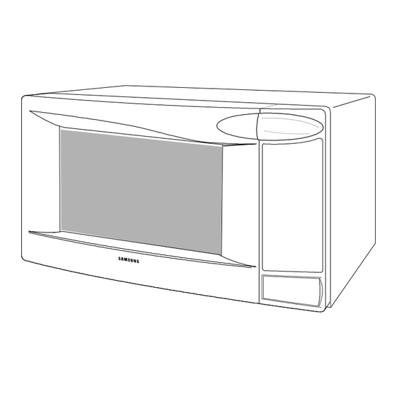
3. Operating Instructions 3-1 Control Panel 3-2 Features & External Views VENTILATION HOLES GRILL LIGHT DOOR LATCHES OPEN DOOR PUSH BUTTON COUPLER SAFETY INTERLOCK HOLES TURNTABLE DOOR 555mm 464mm - 4 -... -
Page 7: Disassembly And Reassembly
4. Disassembly and Reassembly 4-1 Replacement of Magnetron, Motor Assembly and Lamp Cover Air Remove the magnetron including the shield case, permanent magnet, choke coils and capacitors Lamp Thermo S/W (all of which are contained in one assembly). Bracket T.C.O 1. -
Page 8: Replacement Of Door Assembly
4-3 Replacement of Door Assembly 4-3-1 Removal of Door Assembly Remove hex bolts securing the upper hinge and lower hinge. Then remove the door assembly. Upper Hinge Screw Lower Hinge Screw 4-3-2 Removal of Door "C" Insert flat screwdriver into the gap between Door "A"... -
Page 9: Reassembly Test
4-3-5 Reassembly Test After replacement of the defective component parts of the door, reassemble it and follow the instructions below for proper installation and adjustment so as to prevent an excessive microwave leakage. 1. When mounting the door to the oven, be sure to adjust the door parallel to the bottom line of the oven face plate by moving the upper hinge and lower hinge in the direction necessary for proper alignment. -
Page 10: Replacement Of Control Circuit Board
4-6 Replacement of Control Circuit Board 4-6-1 Removal of Control Box 1. Be sure to ground any static electric charge in your body and never touch the control circuit. 2. Disconnect the connectors from the control circuit board. Screw 3. Remove screws securing the control box assembly. -
Page 11: Alignment And Adjustments
5. Alignment and Adjustments PRECAUTION 1. High voltage is present at the high voltage terminals during any cook cycle. 2. It is neither necessary nor advisable to attempt measurement of the high voltage. 3. Before touching any oven components or wiring, always unplug the oven from its power source and discharge the high voltage capacitor. -
Page 12: High Voltage Capacitor
5-4 High Voltage Capacitor 1. Check continuity of the capacitor with the meter set at the highest resistance scale. 2. Once the capacitor is charged, a normal capacitor shows continuity for a short time, and then indicates 9M Ω . 3. -
Page 13: Output Power Of Magnetron
5-8 Output Power of Magnetron CAUTION MICROWAVE RADIATION PERSONNEL SHOULD NOT ALLOW EXPOSURE TO MICROWAVE RADIATION FROM MICROWAVE GENERATOR OR OTHER PARTS CONDUCTING MICROWAVE ENERGY. The output power of the magnetron can be measured by performing a water temperature rise test. Equipment needed : * Two 1-liter cylindrical borosilicate glass vessel (Outside diameter 190 mm) * One glass thermometer with mercury column... -
Page 14: Procedure For Measurement Of Microwave Energy Leakage
5-10 Procedure for Measurement of Microwave Energy Leakage 1) Pour 275±15cc of 20±5° C(68±9° F) water in a beaker which is graduated to 600cc, and place the beaker in the center of the oven. 2) Start to operate the oven and measure the leakage by using a microwave energy survey meter. -
Page 15: Troubleshooting
6. Troubleshooting PRECAUTION 1. CHECK GROUNDING BEFORE CHECKING FOR TROUBLE. 2. BE CAREFUL OF THE HIGH VOLTAGE CIRCUIT. 3. DISCHARGE THE HIGH VOLTAGE CAPACITOR. 4. WHEN CHECKING THE CONTINUITY OF THE SWITCHES OR TRANSFORMER, DISCONNECT ONE LEAD WIRE FROM THESE PARTS AND THEN CHECK CONTINUITY WITHOUT THE POWER SOURCE ON. - Page 16 6-1 Electrical Malfunction(continued) SYMPTOM CAUSE CORRECTIONS Oven lamp and fan motor turn on 1. Misadjustment or loose wiring Adjust door and latch switches. of primary latch switch 2. Defective primary latch switch Oven can program but timer 1. Open or loose wiring of Adjust door and interlock does not start.
-
Page 17: Exploded Views And Parts List
7. Exploded Views and Parts List 7-1 Exploded Views MD11 MD06 MD04 MM01 MM52 MD08 MD05 MM67 MM59 MD17 MD02 MD09 MM07 MM03 MM62 MM65 MM61 MM63 MD07 MM68 MM21 MM69 MM132 MD10 MM72 MM55 MM172 MM60 MM34 MM57 MD01 MM17 MM06 MM71... -
Page 18: Main Parts List
7-2 Main Parts List Code No. Description Specification Q'ty Remark MB01 DE96-00005C ASSY BODY LATCH 2&2 ALL,D/SECSING VE,PP(FH44N),-,-,- MB02 3405-001032 SWITCH-MICRO 125/250VAC,16A,200GF,SPDT MON S/W MB03 3405-001034 SWITCH-MICRO 125/250VAC,16A,200GF,SPST-NO PRI S/W MB04 DE66-90114A LEVER-S/W PP(FH44N),-,-,-,3.5g,NTR,3RD-W MW5592W,- MB05 DE66-40001C LATCH-BODY -,-,-,-,-,NTR,39.2g MB08 3405-001042 SWITCH-MICRO DC 24V,0.3A,150gf,-... - Page 19 7-3 Control and Door Parts List Code No. Description Specification Q'ty Remark MC01 ASSY CONTROL-BOX 120V60HZ,MG1460WA/XAX,WHITE,GRILL S.N.A MC02 DE34-00090L SWITCH MEMBRANE MG1460WA/XAX,-,-,PET,-,120V60HZ,S2,WHITE MC03 DE72-70208C CONTROL-PANEL M1D33/CE2D33,ABS(HR0370U),P/WHT(W9501),- MC04 DE61-70026A SPRING-BUTTON D17,CS,SWP,SWP,PI0.7,PI0.7,PI0.7,-,D17,-,L25.8 MC05 DE66-20281A BUTTON-PUSH 3RD-W B DESIGN,-,T2x37x86,-,-,15g MC06 DE67-40175A WINDOW-DISPLAY 5G,SAN,-,-,-,-,SMG,- MC07 RA-N2LED1-09 ASSY PCB PARTS:MB569...
-
Page 20: Standard Parts List
7-4 Standard Parts List Code No. Description Specification Q'ty Remark DE60-10012A SCREW-TAP TITE -,SWR10,M4,L10,TH,+,-,3,ZPC2,- CONTROL DE60-10012A SCREW-TAP TITE -,SWR10,M4,L10,TH,+,-,3,ZPC2,- EARTH DE60-10024A SCREW-PH -,ZPC3,L8,MSWR10,PH,+,-,M4,-,- DE60-10053A SCREW-TAP PH -,-,FEFZY,-,PH,M4,-,L10,-,- FUSE-HOLDER DE60-10070A SCREW-TAP TH -,-,FEFZY,2-SLOT,TH,M4,-,L12,-,- B-PLTE DE60-10070A SCREW-TAP TH -,-,FEFZY,2-SLOT,TH,M4,-,L12,-,- CN-BOX DE60-10070A SCREW-TAP TH -,-,FEFZY,2-SLOT,TH,M4,-,L12,-,- CV/AIR DE60-10070A... - Page 21 8. P.C.B Diagrams 8-1 P.C.B Diagrams - 19 -...
- Page 22 8-2 P.C.B Parts List Code No. Description Specification Q'ty Remark 3501-001155 RELAY-MINIATURE 24VDC,200MW,3000MA,1FORMA,10MS,10MS RY01 3501-001188 RELAY-POWER 24V DC,0.53W,-,1FormA,9.3ms,10mS RY02 3501-001209 RELAY-POWER 24V DC,0.53W,-,1FORMA,9.3MS,10MS RY04 3708-001551 CONNECTOR-FPC/FC/PIC 14P,1.25mm,STRAIGHT,SN CN04 DE07-00021M LED DISPLAY CSQ-4246G-12,NC2000-GRILL,-,40SEG,5DIGIT,- LED1 DE09-00054A IC MICOM TPM87CH47U,OTP-16K,QFP,-,44PIN,- IC01 DE26-00037A TRANS-L.V SLV-4290U,120V,60Hz,AC17V/7V,-,35*10,PIN,- LVT1 DE30-20016A...
-
Page 23: Schematic Diagrams
9. Schematic Diagrams 9-1 Schematic Diagrams WARNING POWER MUST BE DISCONNECTED BEFORE SERVICING THIS APPLIANCE FUSE CAVITY PRIMARY S/W 250V20A H. V. TRANSFORMER 120V 130V POWER CORD AC 120V/60Hz 120V H. V. CAPACITOR MAGNETRON POWER RELAY (SECONDARY INTERLOCK) 1. INPUT : 120V 60HZ 2. - Page 24 ELECTRONICS ©Samsung Electronics Co., Ltd. November 2001 Printed in Korea Code No. : DE68-02416A...
Need help?
Do you have a question about the MG1480STB and is the answer not in the manual?
Questions and answers