Table of Contents
Advertisement
Advertisement
Table of Contents

Related Manuals for Abbott Afinion 2


Summary of Contents for Abbott Afinion 2
- Page 1 1116554, 1116663 User Manual 1116752 Rev. A 2018/09...
- Page 2 Upon arrival of your Afinion 2 Analyzer we recommend that the serial number along with the software version be recorded in the table provided below. The additional rows in the table are to be utilized if a software upgrade is performed on your Afinion 2 Analyzer. The recorded information will be of great value if and when a question is reported, or the desire to add a new Afinion Test to your analyzer arises.
- Page 3 ™ Afinion 2 System, consisting of the Afinion 2 Analyzer and the Afinion Test Cartridges, is for in vitro diagnostic use only. Afinion 2 Analyzer is a compact multi-assay analyzer for point-of-care testing and is designed to analyze the Afinion Test Cartridges.
- Page 4 4 | US AFINION 2 User Manual ™...
-
Page 5: Table Of Contents
Table of Contents Table of contents Introduction About this user manual Examining the package contents Analyzer System Description Description of the AFINION 2 Analyzer ™ Description of the Afinion Test Cartridge ™ How the AFINION 2 System works ™ Internal process control The analyzer self-test The fail-safe mechanisms External process control... - Page 6 Table of Contents Testing Procedures Operating precautions When operating the analyzer When handling the test cartridge Preparing for an AFINION 2 Analysis ™ Collecting a sample Analysing a patient/control sample Using the operator ID function Entering operator ID Using the patient ID function Entering patient ID Using the control ID function Entering control ID...
-
Page 7: About This User Manual
Introduction About this user manual This user manual will guide you through installation, operation and maintenance of your Afinion 2 Analyzer. The user manual also explains how the analyzer works, describes the quality assurance system and assists you in troubleshooting. -
Page 8: Description Of The Afinion
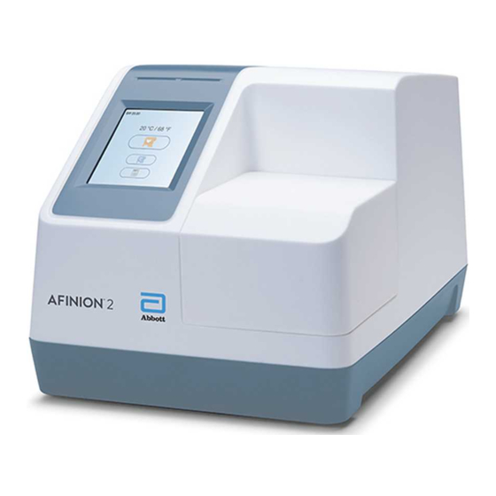
Analyzer System Description Description of the AFINION 2 Analyzer ™ Figure 1 shows the main exterior parts of the Afinion 2 Analyzer. Figure 1 ON/OFF button: Turns the power to the analyzer on and off. Red and green LEDs: Light emitting diodes (LEDs) that indicates whether the analyzer is busy or not. -
Page 9: How The Afinion
External process control Patient ID The Afinion 2 patient ID functionality will, if configured, allow up to four patient ID fields to be entered. The patient ID will be stored with each patient test result in the result records. Operator ID The Afinion 2 operator functionality will, if configured, require the operators to login before testing. -
Page 10: Installing Your Analyzer
Installing your analyzer Place your Afinion 2 Analyzer on a dry, clean, stable and horizontal surface. Make sure that the analyzer is located with sufficient surrounding airspace, at least 5 inches on each side. Placement of Afinion 2 Analyzer should allow easy disconnection from the wall outlet at any time. Acclimate the analyzer to ambient operating temperature (15-32°C, 59-89°F) before use. -
Page 11: How To Power On The Analyzer
How to operate the analyzer The Afinion 2 Analyzer has two main user interfaces, the touch screen and the cartridge chamber. The analyzer is easily operated using the touch buttons that appear on the screen. When a button is touched, its function will be activated. Text messages that appear on the screen will help guide you through the testing procedure. -
Page 12: The Afinion
Configuration The AFINION 2 menus ™ Start-up menu Main menu Patient ID configuration Operator configuration menu menu Screen/beeper Configuration menu Language setting menu Date/Time QC lockout configuration menu menu General settings menu 12 | US AFINION 2 User Manual ™... -
Page 13: Setting The Configuration
Configuration Setting the configuration Before using your Afinion 2 Analyzer you should set the configuration according to your needs. To enter the Configuration menu, do the following: Start-up menu Touch to enter Main menu. Main menu Touch to enter Configuration menu. -
Page 14: Operator Configuration
Configuration Operator configuration The operator ID function is disabled as a default setting by the manufacturer. Touch in the Configuration menu to enter the Operator configuration menu. Operator ID enable/disable Touch in Operator configuration menu to enable/disable operator ID. Select to disable the operator ID function. -
Page 15: Choosing Language
Configuration Choosing language Touch in the Configuration menu to enter the language setting. The default setting by manufacturer is English. Other languages are available. Touch the arrow in the window to view other options. Scroll down until you find the preferred language. Touch to accept and return to the Configuration menu. -
Page 16: Qc Lockout Configuration
Configuration QC lockout configuration Touch in the Configuration menu to enter the QC lockout configuration menu. Touch to configure QC lockout for the assay selected. Touch to configure QC lockout interval. Touch to view/add/delete stored control lots in the control lot database. Select assay for QC lockout configuration Touch the arrow in the window to open the drop down menu. -
Page 17: General Settings
Configuration General settings Touch in the Configuration menu to enter the General settings menu. Touch to erase all content and configurations. Touch to enter Instrument network settings. Touch to enter Connectivity settings. Erase all contents and configurations Touch in General settings menu to erase all contents and configurations. Touch to erase all content and configurations. -
Page 18: Connectivity Settings
(HL7 only) Visit Number (HL7 only) For further information about the connectivity settings, see the Afinion 2 data sheets for POCT1-A, ASTM and HL7 which can be obtained at www.Alere.com or through your local Afinion supplier. 18 | US AFINION 2 User Manual ™... -
Page 19: Why Quality Control Testing
Controls supplied by Alere Technologies AS are recommended for use with the Afinion 2 System. These control kits contain control materials with established acceptable ranges for the Afinion 2 System. If you decide to use controls from another supplier, you will need to determine their precision and to establish acceptable control ranges for the Afinion 2 System. Handling and testing controls Consult the package insert that comes with each control kit for detailed instructions on handling and storage of the control material. -
Page 20: Testing Procedures
- Allow the Afinion Test Cartridges to reach the recommended operating temperature before use. - Power on your Afinion 2 Analyzer so it is ready for the day’s first analysis. - Enter the operator ID (optional). See procedure on page 22. -
Page 21: Collecting A Sample
Testing Procedures Collecting a sample • The patient sample material and control material to be used is specific for each Afinion Test. • The length of the capillary in the sampling device, and thereby the sample volume, might also vary for the different Afinion Tests. •... -
Page 22: Using The Operator Id Function
Testing Procedures Using the operator ID function Entering operator ID If enabled, the operator’s identification (ID) is required before processing an Afinion Test Cartridge (see “Operator configuration”, page 14). Both letters and numbers can be entered (maximum 16 characters). The operator ID will be displayed with the result and stored along with the other specific data for this run (see “Patient and control results records”, page 25). -
Page 23: Using The Control Id Function
Testing Procedures Using the control ID function In quality control testing, a suitable control ID must always be entered. The lot number of the control material is recommended as a suitable control ID. The control ID function cannot be disabled. Entering Control ID It is recommended to enter the control ID during processing of the test cartridge in the analyzer. -
Page 24: Running Controls With Enabled Qc Lockout Function
Testing Procedures Touch the QC lockout status button (padlock symbol) in the Start-up menu to enter the QC lockout status view. Status The information is displayed as a list. Only the assays with QC lockout activated are displayed in this window. Red text indicates expired assays and orange text indicates assays within warning period. -
Page 25: Patient And Control Results Records
Patient and control results records The patient and control results are stored in the memory of the Afinion 2 Analyzer. The last 500 patient results and the last 500 control results are saved in separate records. When exceeding the capacity of 500 results, the oldest result will be deleted. The following parameters are listed for each run: Date and time, run number, patient ID/control ID, operator ID, lot number of test cartridge and the test result. -
Page 26: When An Information Code Appears
Information Codes and Troubleshooting When an information code appears Information codes that might appear during use of the Afinion 2 Analyzer refer to specific information or error messages. The code numbers, the possible causes and actions to take are listed below. -
Page 27: Information Codes Caused By Sample Or Test Cartridge
Action to take Start-up procedure failed Contact your local supplier for assistance. Self-test error. Analyzer Analyzer failure Restart analyzer. If the problem persists, contact your local Afinion 2 supplier. in non- operative mode Self-test failed Restart the analyzer. Analyzer failure Restart the analyzer and run controls. -
Page 28: Other Information Codes
The toll free number is available for use only in the United States of America. Before asking for assistance, please record the following information: • Afinion 2 serial number (SN) – see label on the backside of the analyzer • Software version number – see Start-up menu. -
Page 29: Cleaning And Maintenance
Cleaning the exterior Cleaning the exterior of the Afinion 2 Analyzer should be performed whenever necessary. Most spills and stains can be removed with water or a mild detergent. - Power off the analyzer. Unplug the power supply when the shut down procedure is completed. - Page 30 Alere Technologies AS service representative; (vi) use of the Afinion 2 Analyzer in a manner for which it was not designed, (vii) causes external to the Afinion 2 Analyzer such as, but not limited to, power failure or electric power surges, or (viii) use of the Afinion 2 Analyzer in combination with equipment, components or software not supplied by Alere Technologies AS.
-
Page 31: Analyzer
Technical Specifications AFINION 2 Analyzer Analyzer Size 200 mm W x 186 mm H x 328 mm D Weight 3.4 kg Display Standard LCD colour display with back light and integrated touch panel. Resolution: 240 x 320 pixels. Visible area: 58 x 77 mm. Camera 640 x 480 pixels Capacity of result records... -
Page 32: The Touch Buttons And Their Function
Gallery of Icons The touch buttons and their function Touching a button on the screen will activate the function of this button. All the touch buttons that may appear during operation of the Afinion 2 Analyzer are explained below by their function. - Page 33 Gallery of Icons Menu Touch button Name Function Decrease Decrease contrast/volume. Scroll up View previous Scroll down View next Exit Exit current menu and return to previous screen view. Accept Accept (a setting or a test result). Abort Abort the test result or cancel operation. Add button Add new operator or control lot.
-
Page 34: Other Symbols And Signs
Gallery of Icons Other symbols and signs Other symbols, signs and abbreviations that may appear during operation of the Afinion 2 Analyzer are explained below. These symbols or signs are only inform- ative and can not be activated like the buttons. - Page 35 Symbols and Abbreviations The following symbols and abbreviations are used in the product labeling of the Afinion 2 System. Symbol/Abbreviation Explanation Symbol/Abbreviation Explanation The product conforms to all applicable EC Conformity to the RoHS 2 directive Directives and Regulations Conformity to the technical regulations for...
- Page 36 Alere Technologies AS Kjelsåsveien 161 P.O. Box 6863 Rodeløkka NO-0504 Oslo, Norway www.alere.com ISO 13485 certified company © 2018 Abbott. All rights reserved. All trademarks referenced are trademarks of either the Abbott group of companies or their respective owners. 1116752 Rev. A 2018/09...
Need help?
Do you have a question about the Afinion 2 and is the answer not in the manual?
Questions and answers
Does the manual include detailed specifications and guidelines for performing various validation studies, including carryover studies? I haven't been able to locate?