
Related Manuals for Bresser 7002570


Summary of Contents for Bresser 7002570
- Page 1 Weather Station · PC Weather Station with multifunction sensor Instruction manual...
-
Page 3: Table Of Contents
Contents 1 Imprint ................................ 4 2 Validity information ............................ 4 3 About this Instruction Manual........................ 4 4 Parts overview Multisensor ........................... 5 5 Parts overview Base station and Scope of delivery.................. 6 6 Screen display .............................. 8 7 Before starting operation.......................... 9 8 Setting up power supply.......................... 9 9 Attaching rubber pads .......................... 10 10 Assembling and installing the multifunctional remote sensor .............. 11 11 Signal transmission ............................. 12... -
Page 4: Imprint
Please be aware that any requests or submissions sent directly to the manufacturer cannot be processed. Errors excepted. Subject to technical modifications. © 2019 Bresser GmbH All rights reserved. Reproduction of this document, including extracts, in any form (photocopied, printed etc.) or the use and distribution of this document by electronic means (image file, website etc.) is not permitted without... -
Page 5: Parts Overview Multisensor
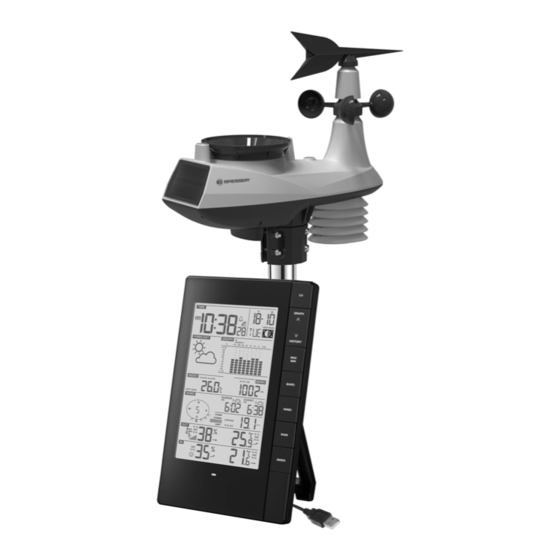
4 Parts overview Multisensor 1 Wind vane 2 Wind cups (Anemometer) 3 Antenna 4 Radiation shield 5 Mounting hole for vertical mounting pole (pipe 6 Hygro-Thermal sensor diameter: 35-40 mm) 7 Battery compartment door 8 RESET button 9 Function indicator 10 Circular level 11 Rain collector (sinkhole) 12 UV Sensor... -
Page 6: Parts Overview Base Station And Scope Of Delivery
13 Solar panel 5 Parts overview Base station and Scope of delivery Illustration 1: All parts of the base station 1 Display 2 Housing 3 SNOOZE/LIGHT button (snooze function 4 CHANNEL button (channel selection) and temporary background lighting) 5 GRAPH/UP button (normal diplay: bar 6 HISTORY/DOWN button (normal display: chart for history data/settings: value single values of history data/settings:... - Page 7 23 SENSOR button (initialize remote sensor 24 CLOCK SET button (manual time setting) data reception) 25 USB cable with microUSB plug (base sta- tion) and USB-A plug (PC) *Weather data transmission requires a PC with Windows 7 or higher and installed 'WEATHER TOOL' software.
-
Page 8: Screen Display
6 Screen display Illustration 2: Screen display of the base station 1 Current time or alarm time 2 Alarm enabled (hours:minutes:seconds) 3 Sync icon (time) 4 Date (day-month or reverse) 5 Weekday 6 Moon phase 7 Bar chart for value display 8 Air pressure alarm enabled 9 Air pressure 10 Sunrise time... -
Page 9: Before Starting Operation
19 Humidity indoors 20 Room climate Indicator 21 Sensor signal status 22 Sensor symbol 23 Wind/storm classification 24 Wind direction 25 Index (heat/dew point/UV/Beaufort) 26 Index value 27 Weather trend 28 AM/PM information in 12-hour time mode 7 Before starting operation NOTICE Avoid connectivity disruptions! To avoid connectivity disruptions between the devices, consider the following points before starting... -
Page 10: Attaching Rubber Pads
9 Attaching rubber pads Attach the supplied self-adhesive rubber pads to the clamps as shown to ensure a firmer fitting of the mounting rod. 10 / 16... -
Page 11: Assembling And Installing The Multifunctional Remote Sensor
10 Assembling and installing the multifunctional remote sensor NORTH 1.5 m 1 U-bolt (2x) 2 Mounting clamp (4x) 3 Washer (4x) 4 Nuts (4x) 5 Mounting pole (1x) Pole placed under egg 6 Battery compartment tray. Please check before disposal of the packaging. -
Page 12: Signal Transmission
NOTICE! During the assembly make sure that the upper part of the wind vane is minimum 1.5 metres off the ground. Use the circular level in the sensor head to ensure a level installation. The windmill must point to the North. Assembly on a vertical or horizontal tube 1. -
Page 13: Setting Up The Station For Weather Data Transmission
(For more information, see the chapter 'Time synchronization with the PC') 15 EC Declaration of Conformity Hereby, Bresser GmbH declares that the equipment type with item number 7002570 : is in compli- ance with Directive: 2014/30/EU. The full text of the EU declaration of conformity is available at the following internet address: www.bresser.de/download/7002570/CE/7002570_CE.pdf... - Page 14 You can consult the full guarantee terms as well as information on extending the guarantee period and details of our services at www.bresser.de/warranty_terms. 14 / 16...
- Page 16 (de preferencia por e-mail: service@bresseruk.com Telephone*: +44 1342 837 098 e-mail). BRESSER UK Ltd e-mail: servicio.iberia@bresser-iberia.es Unit 1 starborough Farm, Teléfono*: +34 91 67972 69 Starborough Road, Nr Marsh Green,...
Need help?
Do you have a question about the 7002570 and is the answer not in the manual?
Questions and answers
Buongiorno sarei curioso di sapere come mai mi è sparito il segnale dei gradi e umidità esterni sebbene mi dia segnale pieno di trasmissione- Grazie
The external temperature and humidity signal may be missing on the Bresser 7002570 despite showing a full transmission signal because the external hygro-thermal sensor (part 6 on the multisensor) may not be functioning correctly, may have a depleted battery, or may not be properly connected or positioned. The full transmission signal only indicates the base station is receiving a signal, but it does not confirm the quality or completeness of the data being transmitted.
This answer is automatically generated