Advertisement
Available languages
Available languages
Quick Links
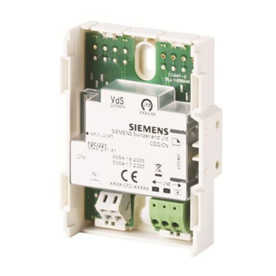
FDCI221
en
Input module
de
Eingabebaustein
fr
Interface d'entrées
es
Módulo de entrada
it
Modulo ingressi digitali
en
Installation
de
Montage
fr
Montage
es
Montaje
it
Montaggio
Fig. 1
A6V10212086_k_--_--
2019-04-02
FDCIO221
Input/Output module
Ein-/Ausgabebaustein
Interface d'entrées / sorties
Módulo de entrada/salida
Modulo in/out digitali
Fig. 4
Fig. 7
FDCH221
Housing
Gehäuse
Boîtier
Carcasa
Contenitore
Fig. 2
Fig. 5
Fig. 3
Fig. 6
Fig. 8
Smart Infrastructure
Advertisement

Subscribe to Our Youtube Channel
Related Manuals for Siemens FDCI221


Summary of Contents for Siemens FDCI221
- Page 1 FDCI221 FDCIO221 FDCH221 Input module Input/Output module Housing Eingabebaustein Ein-/Ausgabebaustein Gehäuse Interface d'entrées Interface d'entrées / sorties Boîtier Módulo de entrada Módulo de entrada/salida Carcasa Modulo ingressi digitali Modulo in/out digitali Contenitore Installation Montage Montage Montaje Montaggio Fig. 2 Fig. 3 Fig.
- Page 2 3.3 kΩ 2 AT 2 AT DC 24 V external DC 24 V external Fig. 9 Fig. 10 Max. DC 30 V FDCIO221 Max. AC 22 V FDCI221 FDCI221 2 AT FDCIO221 FDCIO221 NO/NC not used LINE not used –...
-
Page 3: Installation
Installation Intended use Electric connection The module can use the output for control purposes and NOTICE the input to monitor the status of a potential-free contact. Incorrect polarity and reliability of contact A housing is available to protect the module from environmental influences and to raise the protection Module defect or line interrupt category. -
Page 4: Montage
Montage 4. Befestigen Sie die Kabelverschraubungen M20 am Verwendungszweck Gehäuse und führen Sie die Kabel ein (Fig. 5). Der Baustein kann mit dem Ausgang eine Steuerung 5. Montieren Sie den Baustein mit zwei Schrauben vornehmen und mit dem Eingang den Zustand eines M3 x 12 im Gehäuse (Fig. - Page 5 Montage 4. Fixez les presse-étoupe M20 sur le boîtier et introduisez Application les câbles (Fig. 5). Le module d'interface peut effectuer des fonctions de 5. Montez le module d'interface dans le boîtier avec deux commande par l'intermédiaire de la sortie et surveiller vis M3 x 12 (Fig.3).
-
Page 6: Montaje
Montaje 4. Sujete los prensaestopas para cable M20 en la carcasa Uso previsto e introduzca los cables (Fig. 5). Con la salida, el módulo puede realizar un control y con la 5. Monte el módulo con dos tornillos M3 x 12 en la entrada, monitorizar el estado de un contacto sin carcasa (Fig. - Page 7 2. Individuare i punti di entrata dei cavi nel contenitore e aprirli. Bestell- Détails pour passer Datos de Dati per Details for ordering angaben commande pedido l'ordinazione FDCI221 S54312-F1-A1 Input module Eingabebaustein Interface d'entrées Módulo de entrada Modulo ingressi digitali A6V10212086_k_--_--...
- Page 8 Technical data: see doc. A6V10211122 FDCI221 - Input/output device incl. short-circuit isolator for use in fire detection and fire alarm systems installed in buildings. 305/2011/EU (CPR): EN 54-17 / EN 54-18 ; 2014/30/EU (EMC): EN 50130-4 / EN 61000-6-3 ; 2011/65/EU (RoHS): EN 50581 The declared performance and conformity can be seen in the Declaration of Performance (DoP) and the EU Declaration of Conformity (DoC), which is obtainable via the Customer Support Center: Tel.
Need help?
Do you have a question about the FDCI221 and is the answer not in the manual?
Questions and answers