Table of Contents
Advertisement
Advertisement
Table of Contents

Subscribe to Our Youtube Channel
Related Manuals for Vetronix MTS 3100 Mastertech

Summary of Contents for Vetronix MTS 3100 Mastertech
- Page 1 MTS 3100 Mastertech ® Operator’s Manual...
- Page 2 This entire document and all information contained herein are proprietary, confidential, and exclusive trade secret property of Vetronix Corporation, and shall not be reproduced, duplicated, or copied in whole or in part, or made available to any person, firm, or corporation without the prior written permission of Vetronix...
- Page 3 FCC Compliance This equipment has been tested and found to comply with the limits for a Class B digital device, pursuant to Part 15 of the FCC Rules. These limits are designed to provide reasonable protection against harmful interference when the equipment is operated in a residential installation. This equipment generates, uses and can radiate radio frequency energy and, if not installed and used in accordance with the instruction manual, may cause harmful interference to radio communications.
-
Page 5: Table Of Contents
............Vetronix Service Centers . - Page 6 MASTERTECH CHARACTERISTICS ........3-13 ACTIVATING THE BATTERY BACKED MEMORY .
- Page 7 Mastertech Fails to Power Up ..........C.
- Page 8 TOC-4 Mastertech 3100 Operator’s Manual...
-
Page 9: Introduction
1. INTRODUCTION USING THE MASTERTECH The Mastertech Operator's Manual lists the diagnostic capabilities of the tester and describes the hardware components contained within the Mastertech kit. The Mastertech Operator's Manual also describes how to connect the hand-held tester to the vehicle and how to operate the Mastertech. -
Page 10: Location Of Vehicle Ecus And Test Connectors
Introduction Warnings, Cautions, Notes Enhanced Displays Most TECH 1 cartridges can be used in conjunction with a program card which enables the tester to display data in full-screen Enhanced Mode. Graphic displays such as Bar Charts, Line Graphs, and Oscilloscope displays are available when operating in Enhanced Mode. -
Page 11: Data Memory Retention
Vetronix Service Center and Vetronix Corporation will repair or replace the unit free of charge. This warranty does not cover any part that has been abused, altered, used for a purpose other than that which it was intended, or used in a manner inconsistent with instructions regarding its use including but not limited to the following: •... -
Page 12: Repair Service
(No CODs, please.) When the unit is received at the Vetronix Service Center it will be diagnosed, repaired or replaced, and returned. If the unit is determined to be in warranty, it will be repaired or replaced with no charge and returned freight prepaid. - Page 13 WEEE take-back system for recycling. The WEEE directive concerns all Bosch devices but not external cables or batteries. For more information on the Bosch GmbH Recycling Program, contact one of the Vetronix/Bosch Group sales and service locations listed below.
- Page 14 Introduction Warranty and Repair United Kingdom Advanced Diagnostics Unit 5 Phone: 44 24 76757951 Alliance Close Fax: 44 24 76757952 Attleborough Fields Industrial Estate Email: shaun@advanceddiagnostics.co.uk Nuneaton WWW: www.advanceddiagnostics.co.uk Warwickshire, CV11 6SD Page 1-6 Mastertech 3100 Operator’s Manual...
-
Page 15: Diagnostic Capabilities
2. DIAGNOSTIC CAPABILITIES MASTERTECH KIT OVERVIEW The Mastertech kit consists of a hand-held tester and attachments, which allows the use of one tool for many automotive diagnostic applications. The Mastertech kit is designed so that future automotive diagnostic applications can easily be incorporated into the existing tester. The diagnostic capabilities of the tester components are described in this chapter. - Page 16 Diagnostic Capabilities • Display input sensor read data • Control actuator output data • Display ON/OFF status of switch signals • Test feed-back systems such as the O2 sensor • Command clearing of some ECM/ECU trouble codes • Troubleshoot using the Diagnostic Test Leads •...
-
Page 17: Mastertech Kit Components
3. MASTERTECH KIT COMPONENTS Mastertech kits are available with a variety of components. The items listed below are either included in the Mastertech kit, or are available as accessories through Vetronix Corp. • Mastertech Multi-Function Tester • Multi-Function Tester Program Card •... -
Page 18: Mastertech Features
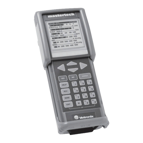
Mastertech Kit Components MASTERTECH FEATURES The Mastertech Multi-Function Tester can be hand-held or placed on a flat surface. An adjustable hand strap on the back provides added security while holding the tester. A built-in support stand allows the tester to be tilted to the most convenient viewing angle when it is not handheld. -
Page 19: Program Cards And Cartridges
Mastertech Kit Components PROGRAM CARDS AND CARTRIDGES The Mastertech uses plug-in program cards and cartridges which contain the software programs for testing specific vehicles and systems. The program cards and cartridges are upgraded periodically to include new vehicles, model years, and systems. Specific operating instructions are provided for diagnostic test functions contained in the program cards or cartridges. -
Page 20: Keypad
Mastertech Kit Components KEYPAD The 27-key keypad allows you to make menu selections or input information. Through the keypad you can select the data you want to see and choose the display format. While performing some tests you can control the operation of certain functions through the keypad. -
Page 21: Mastertech Key Functions
Mastertech Kit Components MASTERTECH KEY FUNCTIONS FUNCTION Similar to the shift key on a typewriter, the keys are used in conjunction with other keys as a modifier. Press the key and hold it down while you press the second key. For example, Turn the tester on. -
Page 22: Display
Mastertech Kit Components DISPLAY The 3" x 3" display allows data to be viewed in several graphic modes and text modes using large and small character sizes. The tester can display data using real-time bar graphs, line graphs, or data lists for several parameters at the same time. -
Page 23: Power Sources
Mastertech Kit Components POWER SOURCES The Mastertech is intended to be powered from the vehicle battery in one of the following ways: • DC Power Cable and vehicle cigarette lighter socket. • Directly from the battery via the DC Power Cable and the optional Battery Adapter Cable. •... -
Page 24: Leds
Mastertech Kit Components LEDs Eight Light Emitting Diodes (LEDs), four red and four green, are located immediately below the display and are visible only when activated. The green light on the right is lit when the tester is in battery charge mode while the display is off. -
Page 25: Instrumentation Port And Devices
Mastertech Kit Components INSTRUMENTATION PORT AND DEVICES The Instrumentation Port (I/P) is used to connect the tester to one or more devices which are used to expand the diagnostic capability of the tester. The I/P connector receives signals which provide a serial communication link from “smart”... -
Page 26: Diagnostic Test Leads
Mastertech Kit Components DIAGNOSTIC TEST LEADS The Diagnostic Test Leads provide a convenient means of signal input measurement. The Diagnostic Test Leads are used for signal input to the DVM function which passively monitors voltage signals from the ECM/ECU, sensors, actuators, harness and connectors. The Diagnostic Test Leads are also used for signal input to the oscilloscope, as well as timing (frequency, duty cycle, pulse width) measurements on vehicle signals. -
Page 27: Rs232 Port And Rs232 Port Devices
Mastertech Kit Components RS232 PORT AND RS232 PORT DEVICES The Mastertech contains an RS232 Input/Output (I/O) serial data connection capable of supporting peripheral devices. The RS232 connection allows the tester to transfer and receive data to and from other RS232 compatible devices such as a remote host computer or serial printer. RS232 Port FIGURE 3-8. -
Page 28: Printer
Mastertech Kit Components PRINTER When the tester is connected to a compatible serial printer, such as the optional VP-411/VP-414, the following functions are available: • Print diagnostic parameters • Print trouble codes • Print test results • Print display information (including bar graphs and plots) TESTER VP-411 / VP-414 PRINTER... -
Page 29: Mastertech Characteristics
Mastertech Kit Components MASTERTECH CHARACTERISTICS ITEM CHARACTERISTIC SIZE 10.2 x 27.9 x 5.1 CM (4.0 x 11.0 x 2.0 INCHES) WEIGHT 1.02 KG (2.25 LBS) WITH BATTERY PACK POWER 2.4 WATTS @ 12 VDC INPUT VOLTAGE 6.5 TO 24 VDC (PROTECTED AGAINST REVERSE POLARITY) KEYBOARD 23 KEY MEMBRANE GRAPHIC DISPLAY... - Page 30 Mastertech Kit Components Page 3-14 Mastertech 3100 Operator’s Manual...
-
Page 31: Activating The Battery Backed Memory
4. ACTIVATING THE BATTERY BACKED MEMORY Before using the Mastertech for the first time, the following steps must be performed in order to activate the NiCad battery pack and the Lithium battery. 1. To activate the NiCad battery pack, see Figure 4-1. - Page 32 Activating the Battery Backed Memory Slide Battery Pack Toward Bottom of Tester Press Tab Down NiCad Battery Pack FIGURE 4-2. Activating Lithium Battery 3. See Figure 4-3 to remove the plastic strip covering the Lithium battery on the back of the tester. Remove Plastic Lithium...
-
Page 33: Getting Started
5. GETTING STARTED INSTALLING A PROGRAM CARD OR CARTRIDGE The Mastertech must be used in conjunction with a program card or Input/Output (I/O) cartridge, such as a TECH 1 Cartridge. The program card or cartridge contains the software that allows the tester to perform the tasks which are unique to diagnosing the various electronic control systems. -
Page 34: Connecting The Tester To The Vehicle
Getting Started APPLICATION CARTRIDGE PROGRAM CARD FIGURE 5-1. Installing Program Card and Cartridge CONNECTING THE TESTER TO THE VEHICLE The Mastertech kit contains the following cables and adapters to connect the tester to the vehicle. • Data Link Connector (DLC) Cable •... - Page 35 Getting Started APPLICATION CARTRIDGE MFT PROGRAM CARD DC POWER CABLE CABLE 24/14 Pin Controller GM 12/14 PIN Area Network (CAN) FORD 7/14 PIN DLC ADAPTER Vehicle Interface DLC ADAPTER CHRYSLER Module SCI 6/14 PIN P/N 02003211 DLC ADAPTER GM 5-PIN 16/24 Pin OBD II ALDL/DLC GM PIN-E...
-
Page 36: Powering The Tester
Getting Started POWERING THE TESTER The Mastertech can be powered by the vehicle 12-volt battery, by the AC 12-volt power supply, or by the internal battery pack. NOTE The right green LED is illuminated when the tester is connected to external power but has not been turned on. -
Page 37: Turning The Tester On And Off
Getting Started CIGARETTE AC/DC LIGHTER ADAPTER (OPTIONAL) DC POWER CABLE DC POWER CABLE BATTERY ADAPTER CABLE (OPTIONAL) BATTERY FIGURE 5-3. Powering the Mastertech TURNING THE TESTER ON AND OFF Connect the tester to one of the power sources listed above, then press the o key. The battery pack allows you to turn the tester on without being connected to external power. -
Page 38: Power-Up Display
Getting Started POWER-UP DISPLAY Verify that the power up display for the program card or cartridge is correct. If the display is correct, follow the instructions in the program card or cartridge operator's manual. FIGURE 5-5. Power-Up Display with Multi-Function Tester Program Card Installed If the Mastertech is powered up without a program card or cartridge installed, the tester displays “NO PROGRAM CARD INSTALLED.”... -
Page 39: Using The Port Connections
6. USING THE PORT CONNECTIONS RS232 PORT The RS232 port is a standard connection for communication between computers and computer peripherals such as printers and remote host computers. RS232 compatible equipment may be connected to the RS232 port via the 10-pin RJ45 connector located at the bottom left end of the tester. The operation of the RS232 functions are dependent on the program card or cartridge and the RS232 device being used. -
Page 40: Instrumentation Port
Using the Port Connections INSTRUMENTATION PORT The Instrumentation Port connection is a 10-pin RJ45 “phone plug” connector on the bottom right of the tester. The Instrumentation Port supports the use of the Diagnostic Test Leads and other I/P devices. Instrumentation Port FIGURE 6-2. - Page 41 Using the Port Connections Diagnostic Test Lead Adapter Diagnostic Test Lead Diagnostic Test Lead Tips FIGURE 6-3. Diagnostic Test Lead Set and Adapter Mastertech 3100 Operator’s Manual Page 6-3...
- Page 42 Using the Port Connections Page 6-4 Mastertech 3100 Operator’s Manual...
-
Page 43: Finishing Up
7. FINISHING UP After using the Mastertech, a few simple steps will help you leave the vehicle electronic system(s) in the proper state and also ensure that you get the most use out of your diagnostic tools: 1. Reconnect all hoses, connectors, spark plug wires, fuel lines, etc. that were disconnected from the vehicle during testing. - Page 44 Finishing Up adapters, or cables in water. Avoid using harsh solvents such as petroleum based cleaning agents, Acetone, Benzene, Trichloroethylene, etc. Although the tester and accessories are water resistant, they are not waterproof; thoroughly dry them prior to storage. Always clean the tester screen by wiping vertically only. Never use a circular motion on clear plastics. Page 7-2 Mastertech 3100 Operator’s Manual...
-
Page 45: Battery Charging And Replacement
8. BATTERY CHARGING AND REPLACEMENT The Mastertech contains two types of batteries: a set of rechargeable Nickel-Cadmium (NiCad) batteries and a replaceable Lithium battery. NICAD BATTERY PACK The NiCad batteries are housed in a removable battery pack located on the bottom underside of the tester. For normal use, the tester should be powered from the vehicle's cigarette lighter or battery adapter cable, or by the AC 12-volt adapter. -
Page 46: Charging The Battery Pack
NiCad rechargeable batteries. This type of battery is available at certain electronic supply stores, or may be ordered from the nearest Vetronix Service Center listed in the Introduction. When replacing NiCad batteries, always replace all six cells. This will result in maximum battery life. - Page 47 Battery Charging and Replacement To replace the batteries: 1. Disconnect the power supply cable from the vehicle and from the tester. 2. Press P x to turn the tester off. 3. Press the tab at the bottom end of the battery pack while pulling the battery pack toward the bottom of the tester.
-
Page 48: Lithium Battery
Battery Charging and Replacement NOTE NiCad batteries are recyclable. Under various state and local laws it may be illegal to dispose of NiCad batteries in the municipal waste system. Check with local solid waste officials in your area for recycling options or proper disposal methods. - Page 49 Battery Charging and Replacement 3. The round Lithium battery is located under a plastic cover beneath the battery pack on the back of the tester. 4. To remove the NiCad battery pack, press the tab at the end of the battery pack while pulling the battery pack toward the bottom of the tester.
- Page 50 Battery Charging and Replacement Page 8-6 Mastertech 3100 Operator’s Manual...
-
Page 51: Understanding Rs232 Communications
A. UNDERSTANDING RS232 COMMUNICATIONS RS232 is a standard in the computer industry for serial communications between computers and peripheral devices. Virtually all small computer systems have at least one RS232 port. RS232 links are used to communicate with printers, display terminals, modems and many types of test equipment. An RS232 communication link is a serial link as opposed to a parallel link. -
Page 52: Rs232 Interface Signals
Understanding RS232 Communications RS232 INTERFACE SIGNALS SIGNAL NAME INPUT/OUTPUT CONNECT TO: NUMBER NOT USED OUTPUT CARRIER DETECT INPUT CARRIER DETECT TRANSMIT OUTPUT RECEIVE RECEIVE INPUT TRANSMIT SIGNAL GROUND SIGNAL GROUND INPUT NOT USED a. CTS and RTS are connected together inside the tester, but are not used as handshake signals by the tester. PIN 1 PIN 10 RJ45 10-Pin Modular Phone Connector... -
Page 53: If You Are Having Aproblem
B. IF YOU ARE HAVING A PROBLEM If you have a problem using the Mastertech and the program card, first select SELF TEST from the program card SETUP MENU and perform all of the Self Tests. This section is intended to help you get back on track if the Mastertech appears to be operating abnormally. Examples of most of the displays which you might see under abnormal conditions are shown. -
Page 54: Error Message Is Displayed
If You Are Having a Problem ERROR MESSAGE IS DISPLAYED Most Likely Cause • Vehicle ignition switch is turned off. • Tester not connected to vehicle DLC. • DLC adapter or cable is malfunctioning. • Loose connections. Recommendations • Make sure vehicle ignition switch is in the ON position. •... -
Page 55: Mastertech Does Not Pass All Self Tests
If You Are Having a Problem MASTERTECH DOES NOT PASS ALL SELF TESTS Most Likely Cause • Tester is not receiving power from vehicle. • Loose connections. • Program card is not installed. • Tester is connected to the vehicle DLC. •... - Page 56 If You Are Having a Problem DC Power Cable Fuse Power Plug Terminal Power Plug Cover FIGURE B-1. DC Power Cable Plug Page B-4 Mastertech 3100 Operator’s Manual...
- Page 57 C. GLOSSARY AND ABBREVIATIONS TERM DEFINITION Alternating Current BAUD RATE The speed at which data is transferred over a serial data link. Bits per second. Unit used for baud rate. CURSOR Highlighted text or data on the display screen. Same as Marker. DATA LIST A mode of operation.
- Page 58 Glossary and Abbreviations TERM DEFINITION Light Emitting Diode MARKER Highlighted text or data on the display screen. Same as Cursor. NICAD Nickel Cadmium rechargeable batteries. Oxygen On Board Diagnostics Receive RJ45 A modular phone connector. RS232 Same as RS232C. RS232C The most standard serial communication interface used in the computer industry.
- Page 59 INDEX connecting description 3-10 usage adapters display contrast Tech 1 backlight battery lithium enhanced mode display activating error message display description replacing NiCad battery pack activating charging help screens description powering replacing testing usage instrumentation port vehicle battery adapter cable blank screen display keypad cables...
- Page 60 Mastertech kit components description Matertech self tests notes power source power up failure precautions printer 3-12 printer failure program card installing RS232 communication RS232 port 3-11 self tests failure perform tester. See Mastertech troubleshooting warnings warranty Index-2 Mastertech 3100 Operator’s Manual...
Need help?
Do you have a question about the MTS 3100 Mastertech and is the answer not in the manual?
Questions and answers