Domino F Series User Manual
Hide thumbs
Also See for F Series:
- Product manual (220 pages) ,
- Product manual (228 pages) ,
- User manual (44 pages)
Table of Contents
Advertisement
Quick Links
Advertisement
Table of Contents

Related Manuals for Domino F Series


Summary of Contents for Domino F Series
-
Page 2: Table Of Contents
CONTENTS F-SERIES LASER CODER ..............4 CONTENTS OF THE EC DECLARATION OF CONFORMITY ...5 CONTENTS OF THE EU DECLARATION OF INCORPORATION ..7 CERTIFICATION ................10 HEALTH AND SAFETY ..............11 GENERAL ..................11 SPECIFIC DANGERS ................12 Electrical Energy ................12 Laser Radiation ................13 AIMING BEAM / PILOT LASER ............14 HARMFUL DUST AND VAPOURS ............14 TOUCHING THE LENS ..............14 Scan Head Mirrors ..............15... - Page 3 Status Bar ................36 General Functions ...............37 Initial Setup ..................38 Display Settings ..............38 Setting the Master Clock ............38 Security Management ..............39 Creating and Editing a Message ..........40 Add Text .................40 Add a New Barcode ..............41 Add an Image ................41 Add a New Variable ..............42 Add a New Clock ..............43 Add a New Counter ...............43 Add a New Prompted Field ...........45...
- Page 4 WARNINGS: (1) As supplied, this coder is a class 4 laser product. During operation, it will emit up to 40 watts of pulsed invisible laser radiation at a wavelength between 1030 and 1120 nanometers. Avoid eye or skin exposure to direct or scattered radiation.
-
Page 5: F-Series Laser Coder
This manual has been produced for use in the operation of the Domino F-Series Laser Coder and to reinforce and complement any training program available with the product. It is not designed to replace any such training program. -
Page 6: Contents Of The Ec Declaration Of Conformity
Contents of the EC DECLARATION OF CONFORMITY (in accordance with ISO/IEC 17050-1) No. EPT009665/2 Issuer’s name: Domino Laser GmbH, Germany Issuer’s Address: Fangdieckstrasse 75a, 22547 Hamburg / Germany Object of the declaration: F-Series laser marking system consisting of: Controller F220i (BCP7), Laser Unit and optional TouchPanel. - Page 7 2006/95/EC: Low Voltage Directive 2004/108/EC: EMC Directive 2011/65/EU: RoHS2 Directive Additional Information Compliance is dependent upon installation and use in accordance with the Product Manual supplied.
-
Page 8: Contents Of The Eu Declaration Of Incorporation
Fangdieckstrasse 75a, 22547 Hamburg, Germany Person authorised to compile the relevant technical documentation, who must be established in the Community: Research & Development Department, Domino Laser GmbH Object of the declaration: F-Series laser marking system consisting of: Controller F220i (BCP7), Laser Unit and optional TouchPanel. - Page 9 2004/108/EU Directive 2004/108/EC of the European parliament and of the Council of 15 December 2004 on the approximation of the laws of the Member States relating to electromagnetic compatibility and repealing Directive 89/336/EEC 2011/65/EU Directive 2011/65/EU of the European parliament and of the Council of 8 June 2011 on the restriction of the use of certain hazardous substances in electrical and electronic equipment (recast)
- Page 10 EN 61326- Electrical equipment for measurement, control 1:2006 and laboratory use - EMC requirements - Part 1: General requirements (IEC 61326-1:2005) EN ISO Safety of machinery - Safety related parts of 13849-1:2008 control systems - Part 1 Published other applied technical standards and specifications ÖNORM EN Lasers and laser-related equipment - ISO 11252...
-
Page 11: Certification
CERTIFICATION Industrial Laser Unit for Marking: Controller F220i (BCP7), Laser Unit F220i. Approved by Certificate No.: CU72150806 01... -
Page 12: Health And Safety
The equipment conforms to current technology and approved safety requirements. Domino F-Series laser marking systems are produced by Domino Group company; Domino Laser GmbH Germany. For Sales and support, contact Domino. -
Page 13: Specific Dangers
• These personnel are regularly instructed in all matters concerning appropriate labour safety and environmental protection, and that they are familiar with the product manual, particularly the safety instructions contained therein • Any safety and warning signs on the laser marking system must not be removed and must remain in a readable condition. -
Page 14: Laser Radiation
Laser Radiation Laser radiation can pose a risk to eyes and skin. The danger is not only posed by direct laser radiation, but also by scattered radiation and reflections from the work piece or the packaging machine. The degree of injury depends on the duration of the effect, the power and the wavelength of the laser. -
Page 15: Aiming Beam / Pilot Laser
Class 4 The accessible laser radiation may be visible or invisible. Direct and diffuse radiation is extremely harmful to eyes and skin and can pose a fire risk if projected onto combustible materials. The F-Series laser marking systems, taken by themselves, are Class 4 and must not be used until suitable, interlocked guarding is fitted to achieve a Class 1 laser installation that physically prevents access to the... -
Page 16: Scan Head Mirrors
Scan Head Mirrors Never touch the mirrors of the scan head. The mirrors are inside the scan head and there is a small risk of touching them when cleaning the lens. The mirrors for the i-Tech 15 scan head are made of Beryllium. If the mirrors have been touched accidentally, wash hands thoroughly with water and soap. -
Page 17: Laser Marking Process
Laser Marking Process Potential fire risks could result from examples as listed below. This list is not considered to be complete. Local conditions must be considered as well. • Printing on not specified material (e.g. easily inflammable or explosive materials). •... -
Page 18: Guarding
Guarding The following type of guarding, using the recommended materials and construction techniques, is required to achieve a safe installation. WARNING: Never install a laser in such a way that the lens points to a door or in the direction of an operator. -
Page 19: Visor Guards
Visor Guards Visor guards are required to prevent the escape of scattered radiation. Often the access guarding can be designed to perform this function without the need of an extra guard. Access/Visor Guard Scattered Radiation Laser Head Substrate Scattered Lens Laser Beam Path Radiation WARNING:... -
Page 20: Materials
Materials All guard materials must be opaque to 1040 to 1200 nanometers wavelength laser light produced by the fibre laser. Guards may be metallic and non-reflecting, however if a see-through guard is required a material opaque 1030 to 1200 nanometers wavelength laser light must be used. -
Page 21: Beam Delivery Cable (Fibre)
Beam Delivery Cable will be subject to high levels of acceleration, torsion and twist, or combination thereof. If this is a requirement for the integration, please contact Domino to discuss the application in more detail. The minimum bedding radius (r) for the fibre is 75mm. -
Page 22: Interlock Switches
Operation of the product with safety guards removed may result in hazardous exposure to laser radiation. These labels are supplied with the laser system. Additional labels are available from Domino Printing Sciences plc as part of the Guarding Labels Kit, Part Number L007628. -
Page 23: Operation
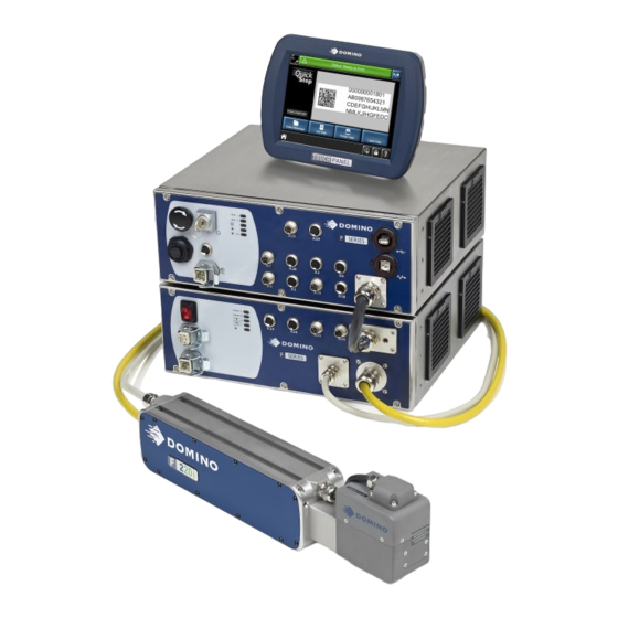
OPERATION F-Series laser Marking System Optional TouchPanel BCP 7 Controller Laser key switch Laser Unit (Laser Box) On/Off Switch Laser Fibre Mains connector Scanner Head Laser Unit (Laser Module) Laser Lens Beam Delivery... -
Page 24: Controls And Indicators
Controls and Indicators The User Interface, Indicator Lamps and Software icon functions are described in the following paragraphs: TouchPanel and Interface The software is operated via a PC keyboard, TouchPanel or Web Browser. An entry is confirmed with the left mouse button if PC or Web browser are used. -
Page 25: Indicator Lamps
Indicator lamps Interlock 1 Interlock 2 PC Ready Printer Ready Printer Busy • Interlock 1 - Illuminates when the interlock 1 is closed. • Interlock 2 - Illuminates when all the interlocks are closed. • PC Ready - Illuminates when the internal PC is ready. •... - Page 26 Power supply LED on the front of the laser unit. To scanner head Laser Module without Shutter Option Power supply LED on the front of the laser unit. Shutter LED To scanner head Shutter LEDs on the front of the laser unit (only with shutter option) Illuminates when shutter is open Laser Module with Shutter Option...
-
Page 27: Additional Indicators Laser Unit F220I
Additional Indicators Laser Unit F220i Interlock Indicator 1 Interlock Indicator 2 Shutter Preparation / Error Indicator Shutter State / Error Indicator Laser Indicator Interlock Indicator 1 and 2 Lit GREEN Interlock 1 and 2 respectively are closed. Both interlock 1 LED and Wrong order was in the interlock 2 LED are alternating interlock loops e.g. - Page 28 Shutter Preparation / Error Indicator Blinking GREEN Waiting for start command. Lit GREEN Ready. Lit RED A shutter malfunction is present Blinking RED A shutter malfunction was detected but no more present. Blinking ORANGE A shutter malfunction was detected - waiting for start command.
- Page 29 Shutter State / Error Indicator Lit YELLOW Shutter is open, caution laser radiation is possible! Lit RED Shutter temperature display (after power-up only). Lit RED (permanent) shutter feedback cross-check failed. Flashing RED while the Shutter is close to over GREEN Shutter preparation temperature.
- Page 30 Laser Indicator / Error Indicator Lit YELLOW Laser source ready for emission. Lit RED (error) Laser is not (correctly) started. 1x Flashing YELLOW Laser modulation (print activity) missed. 2x Flashing YELLOW Laser modulation (print activity) not permitted. 3x Flashing YELLOW Laser modulation (print activity) missed AND not permitted.
-
Page 31: Switching On And Off
Switching On and Off WARNINGS: (1) The laser marking system must only be used for its intended purpose. (2) The laser marking system may only be operated by trained personnel. (3) Operation is only allowed with all required cables connected and all parts mounted. Do not disconnect any cables during operation. -
Page 32: Switching Off The Laser Head
Switching Off the Laser Head • Turn the key switch from position “1” to position “0”. The laser hardware is switched off. Switching Off the Control Unit • Press the On/Off button at the BCP7 controller. The computer will immediately switch off. •... -
Page 33: F-Series Connectivity
F-Series Connectivity The F-Series is operated either via a remote TouchPanel or via a PC running on Microsoft Windows 7® or Windows 8® with installed QuickStep software. To connect to one D-Series, the TouchPanel is connected to the X59 TouchPanel connector of the controller. The TouchPanel then displays the UI relating to that printer. -
Page 34: Webserver
A list of favourite remote printers can be created, as follows: From the printer’s list screen, press the Lock button and select Unlock UI Settings, enter the password (Domino1). Press Settings and select Favourite as the connection method. Press Add Favourite and fill in the required fields manually or get a favourite printer from broadcast Select a printer from the Broadcast list. -
Page 35: Quickstep Interface
Quickstep Interface Home Screen When starting the printer, the following Home screen is displayed. Status Bar Status Icons Start/Stop Button Zoom Toolbar Live Message Preview Main Menu Selection Buttons Lock Printer Name... - Page 36 Status Icons: Displays current status of printer, e.g: • Laser active (Laser is busy - laser emission!) • USB device connected (USB device connected to controller or TouchPanel) • Dongle connected (Pharma or Service dongle connected) Status Bar: Displays printer and alert status. If more than one alert is present, the highest priority alert is displayed.
-
Page 37: Status Bar
Lock Button: • Locks the screen to prevent accidental changes • Login and logout • Disconnects from printer Printer Name: Shows the printer which is being currently controlled Status Bar The status bar displays informal warning and error messages in different colours: •... -
Page 38: General Functions
General Functions The following illustration shows the Global Print Settings screen and the various screen areas. Status Icons Status Bar Start/Stop Button Screen Title Scroll By Tabs Line Scroll By Page Breadcrumb navigation Click long on a button to get a description. Click long on a button of the Settings area to move this button to the Home screen. -
Page 39: Initial Setup
Initial Setup The initial setup configures the overall look of the interface and also configures basic settings and presets for printer operation. Display Settings Home > Settings > Regional > Language and Keyboard Set: • Language. • Keyboard layout. • IME Scheme. •... -
Page 40: Security Management
Extended system parameter settings can only be changed after entering the Administrator password. This password is only known by employees authorised by Domino. Note: If unauthorised changes are performed, the warranty will be invalidated. Changing the passwords after the initial installation is recommended. -
Page 41: Creating And Editing A Message
Creating and Editing a Message Add Text Select Messages > New Message or Settings > Message Editor to open the Message Editor. Press on the screen within a specific area of the Message Editor where you require the item to appear. A cross hair will appear at this location. -
Page 42: Add A New Barcode
Add a New Barcode To add a barcode to the message: Press on the screen within a specific area of the Message Editor where you require the item to appear. A cross hair will appear at this location. Select the Add Barcode icon and select the type and specification required from the list and editable text boxes. -
Page 43: Add A New Variable
Add a New Variable Message or system variables may be added. Message variables may only be used in the message in which they have been created. System variables can be used in all messages. • Message variables are created via Home > Settings > Message Editor >... -
Page 44: Add A New Clock
Add a New Clock To add a new offset clock to the message: Press on the screen within a specific area of the Message Editor where you require the item to appear. A cross hair will appear at this location. Select the Add icon. - Page 45 In the Step Control box, select the option required to activate the increment: Print Start User Input (Rising Edge)- specify the User Input to be used User Input (Falling Edge)- specify the User Input to be used In the External Reset box, select None, Mark Enable, Application Start, Message Load, User input Rising Edge, User input Falling Edge.
-
Page 46: Add A New Prompted Field
Add a New Prompted Field Prompted text fields may be inserted into messages. The content of these text fields is entered in QuickStep after sending the message to the printer.The content format has to be specified when creating these text fields in a message in the Message Editor. To add a new prompted field to the message: Press on the screen within a specific area of the Message Editor where you require the item to appear. - Page 47 Mandatory any character Optional any character Optional currency symbol €, $, £ or ¥ & Mandatory any character or space Review the entered information and select the green tick icon if correct or press in the required field to add or change values. (10) Select the green tick icon to enter the prompted field into the message.
-
Page 48: Add A New Link
Add a New Link To add a new link to the message: Press on the screen within a specific area of the Message Editor where you require the item to appear. A cross hair will appear at this location. (2) Select the Add icon. -
Page 49: Undo / Redo
Undo / Redo Undo Redo Undo re redo the last editing steps in the message editor including change of settings or parameter settings. Note: Creating a new message clears the undo cache - no undo to the last message is possible. File Save as Laser... -
Page 50: Edit
Edit Edit Text Alignment Delete Object Select Edit Object Font Properties Edit menu for a text object. Edit Text - Opens the keyboard to edit the text content. Select Font - Opens the list of available fonts to select a font. Alignment - Sets the alignment of the object. -
Page 51: Move
Move Select an object in the editor by clicking on it and move it in the desired direction by clicking on the arrow icons. Drag and drop can also be used.Select and hold the item within the message and move it to the desired location. Zoom Zoom in Fit height... -
Page 52: Re-Order Visual Items
Re-order Visual Items Sets the order of objects to print. Select an object of the list and use the arrows to change the order. Item Selection List Selects multiple or all objects of a message. Select the items of the list to be selected. -
Page 53: Message Store And File Management
Message Store and File Management Selecting an Existing Message Note: Where no message is selected for printing, no live message will be displayed in the Home screen. Select the Messages button to open the Message Store. Select the required message from the list. Choose to Edit, Preview or Send to Print. -
Page 54: Maintenance
MAINTENANCE Checking Fans and Air Vents WARNING: Before undertaking any work on the laser marking system, unplug the mains power. The fans are located at the sides of the control unit. A fan defect immediately poses a danger of overheating that may result in damage to the control unit, therefore the fans must be checked once a month. -
Page 55: General Cleaning
Cotton Swab Lens Assembly Inspect the cotton swab. If dirt or oil is present, repeat steps (1) to (3). Use the dry end of the cotton swab to lightly wipe excess liquid from the lens. General Cleaning WARNING: The laser marking system and the connected installation must be switched off with the mains supply to the laser marking system disconnected. -
Page 56: Service: Replacement Of Components
Service: Replacement of Components Applications without Shutter Maximum cycles of E-Stop Relay PNOZ S4 15 Million (opening of guard door when laser is printing) Maximum cycles of E-Stop Relay PNOZ S4 100 Million (opening of guard door when laser is not printing) Applications with Shutter Maximum cycles of Shutter... -
Page 57: Fault Finding
(underflow.) in time. the field. List buffer Internal Fault. Restart the system. Contact repeat count Domino. fail. Maximum print The maximum Restart the system. Contact to print distance between Domino. distance print go signals has exceeded. - Page 58 Status Cause Suggested Action Message Scanhead The scanhead is Restart the system. Contact temperature cold. Domino. out of valid range. Scanhead The scanhead is Wait for the heaters in the warming up - cold. scanner motors to warm the please wait.
- Page 59 Wait for the printer to be enabling. switched on but ready. warming up. 580 Inconsistent The laser start input Restart the system. Contact Laser On State level is being Domino. overridden by a user interface laser on selection or by a fault message.
- Page 60 594 Safety Relay There was a laser Make sure the interlocks are Fault start command closed before giving the laser present while one or start input. both (CAT3/4) interlocks where not closed. Note: For all other errors or messages contact Domino.
Need help?
Do you have a question about the F Series and is the answer not in the manual?
Questions and answers