Table of Contents
Advertisement
Advertisement
Table of Contents

Summary of Contents for Red Technology MAGIC-2
- Page 2 REV. 100602 RED TECHNOLOGY http://www.redt-magic-engraver.com 3F, 1314 Gwanpyeong-dong Yuseong-gu Daejeon, Republic of Korea, 305-509 TEL:+82-70-7011-0905 FAX: +82-42-673-0905...
-
Page 3: Table Of Contents
Other Cautions 1. Product Configuration and Installation - Parts - Specification - Program Installation - Machine Installation - MAGIC-2 - How to Use Vise - Calibration - Changing Tool 2. How to Use Program - Tool Bar - Object Properties... -
Page 4: Caution Related To Electric Power
Caution Surely observe the below contents for safely using product It is for user’s safety and preventing property damage Please rightly use product after carefully reading the below matters In the case of not observing operation instruction, it may result in bodily injury and property loss. -
Page 5: Caution In Using
Caution in Using Please don’t put materials, vessel While engraving machine is in operation, cutter is rotated by high speed. Please never having water, small steel materials, put body part or other materials inside the etc, on engraving machine engraving machine ... -
Page 6: Product Configuration And Installation
Product Configuration and Installation Parts The following accessories are included in the product package. PART FIGURE QTY. USAGE NAME Dragging Used to mark character or image on 1 EA Tool metal surface. Additional 1 SET Used to grip thick material like bottle. Clamp Used to supply power to machine Adapter... -
Page 7: Specification
Product Specification AC Input 100~240V, 50/60Hz Power consumption External Dimension 260mm(W) × 233mm(H) × 325mm(D) Workspace Size 123mm(X) x 90 mm(Y) x 30mm(Z) Resolution 0.005mm (X,Y), 0.00125(Z) Weight 18Kg 1 – 36mm/sec (XY), 1 – 18mm/sec (Z) Feed Rate 5 – 40 ºC Temperature Humidity 10 - 90 %... -
Page 8: Program Installation
Program Installation 1. Press “Next” 2. By pressing “install”, program installation is automatically started 4. By pressing “Finish”, program installation is 3. During installing, file is copied to hard disk completed 6. Press “NEXT” 5. When program installation is finished, USB driver installation window is popped up. - Page 9 Model Selection When the program is run first after the installation, "Select Machine Model in Use" window will be popped up. Select proper model in the list. If serveral different models are being used, select all the models from the list. ※...
-
Page 10: Machine Installation
Machine Installation MAGIC-2 is desktop CNC engraving machine and only when it is connected with PC and used together with program, it can engrave. USB cable, which is provided as part, is inserted to USB port of engraving machine’s left side and PC back or front side. -
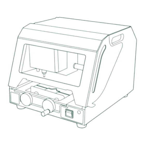
Page 11: Magic-2
MAGIC-2 Name for Each Part Explanation for Each Part Tool Holder Fixes engraving tool. Vise Fixes Metal / Pendant engraving material. Vise Handle Tightens or loosens vice. Power Switch Turns engraving machine on/off. Operation Key Moves engraving position and stop engraving. - Page 12 STOP If the machine is in engraving state, pressing this button will cancel (in engraving state) engraving. Stopping the engraving job, it will return to home position. START If the machine is in engraving area positioning state, press this button ( in positioning state) for more than 1 second to start engraving.
- Page 13 MAGIC-2 Operation When turning on MAGIC-2, it performs self-diagnosis as following and if there is not any problem, it is in stand- by condition with confirmation sound, short “beep-beep-beep”. (1) Self-diagnosis order in power ON If there is axis detected by sensor, it moves itself out of detection area...
-
Page 14: How To Use Vise
How to Use Vise Fixing Material to Engrave Because vise fixing part is step-like, you just fix it on step suitable for material size. When you turn vise handle to the left, vise is widened and otherwise, it is tightened. Tightening Direction Widening Direction Auxiliary Vise... -
Page 15: Calibration
Calibration There exist three calibrations in MAGIC-2. 1. Probe Calibration 2. Laser Pointer Calibration 3. Vise Center Calibration You can enter each setting modes by pressing a certain key when the power is switched on. Entering Calibration Mode When turn power switch on, press key for certain period of time. - Page 16 Laser Pointer Calibration 1. Change the tool to dragging tool. 2. Turn power ON pressing , and then release the button as soon as machine beeps. 3. Tool will move to center of vise, then draw cross(+) mark on the material. And red laser pointer will be lit.
- Page 17 Vise Center Calibration: 1. Prepare a rectangular or circular material and mark a dot on the center of the material with marker pen. ● 2. Turn power ON pressing , then release the button as soon as machine beeps. 3. Tool will move to the center of vise, then red laser pointer will be lit. ●...
-
Page 18: Changing Tool
CHANGING TOOL Using 2.5 T-Wrench that comes with the machine, take out the tool loosing tool fastening bolt and fasten it after new tool is inserted. Tool length is not so important, but 10~20mm is recommended. ◈ EXCHANGING TOOL 10~20mm ☞... -
Page 19: How To Use Program
2. How to Use Program When program is run, the below window is popped up, program window is differently shown for each case of selecting object and not selecting object and at this time, each part name is as following. Program Screen Menus Tools... - Page 20 When Rotating Object Rotation information registration Object When Selecting Tool Path Tool path registration information Tool pass...
-
Page 21: Tool Bar
Tool Bar Arrangement Tool Straight line/curved line/curve line circle/ellipse/phi circle/ellipse/phi Rectangle Rectangle/round-shape rectangle Polygon Polygon Left and right reverse Left and right reverse turn of selected character turn Rotation Rotate selected object Color reverse Color reverse of selected character 90˚ rotation Rotate selected character by 90˚... - Page 22 Object Tool Open template Open design sample Selection Select object Input/edit character Input or edit character Circular deposition Input round character character Brush line Free drawing Image Insert picture Erase line Erase line from selected object Node edit Edit circle, rectangle, polygon, etc. Generate tool path by object’s frame Cutting tool path generation Hatching...
-
Page 23: Object Properties
Screen Zoom & Moving Tool Zoom in by one step Zoom out by one step Select ratio between zoom-in and zoom-out Magnify a area dragged by mouse Magnify selected object size Adjust screen to total page Move screen Object Properties Font Size Magnify or reduce selected character by one step... -
Page 24: Rotation Properties
Selected object’s line thickness Selected object’s line shape Selected object’s line color Fill color inside Fill shape inside Rotation Properties Rotate selected object by one degree. When inputting your wanted rotation angle pressing button, object is rotated as much as input angle Rotate selected object as much as input angle. -
Page 25: Tool Path Creation Creation
Tool Path Creation Tool Path Type When creating tool path for the left drawing, tool path is produced as follows according to each type. Engrave character frame. Engrave character surface. Outline Hatching (Cutting) Engrave character’s center. Engrave character’s inside frame. Inline Single line... - Page 26 ToolPath Creation Properties Engraving Method Hatching interval, depth, engraving speed, etc, for each material are set up in advance. Therefore, you don’t have to appoint hatching interval, depth, engraving speed, etc. every time and if you select engraving option, value appointed in advance is automatically set up.
- Page 27 If checked, engraves outline after finishing hatching. It not, mark hatched only. Retouch Outline This option is recommended when engraving large object. For small engraving like small text, better engraving quality can be made by turning off this option. Appoint cutting depth. Generally, because material may be bent and inclined, only when you should appoint depth 0.1~0.2mm deeper than cut material’s thickness, you can perfectly cut it.
-
Page 28: Medal Marking
Medal Marking TOOL CLAMP Basic Clamp 1. Measure material size Dragging Tool Vertical size Horizontal size 2. Fix material to vice’s center 3. Select engraved material’s shape from template list and input template size. And then, click “OK”... - Page 29 4. When template is shown, press [character input/edit] and click your wanted position by mouse. And then, input your wanted sentence. 5. When character input is finished, press tool bar [selection] and enter object selection mode. And then, select input character string and edit object’s size, font, size, etc. In order to arrange object to the center of working area, click button [center arrangement of working area]...
- Page 30 6. When drawing is finished, click “Hatching Tool path” like the below figure. 7. When “Hatching Tool path” window is shown like the below figure, appoint tool, hatching interval and depth, click “Create Tool Path”. [Brief View] [Detail View]...
- Page 31 8. “Tool path” object is generated like the below. 9. Click button for tool path data transmission to start engraving. 10. “Output” window is shown, appoint communication port and how to measure material and then, click “Start Engraving”...
- Page 32 Measure material’s height. Surface Height Measure material’s inclination. Surface Slope Height is not measured. At this case, as for material height, pre-measured height is applied. In previous engraving work, if you don’t put material out of Skip vice, you can save measuring time by selecting this option. Appoint if engraving position is readjusted.
- Page 33 Marking Area 13. Once position is set, press key for 2 seconds to start engraving.
-
Page 34: Loading Image And Converting It To Engravable Image
Loading Image and Converting It to Engravable Image A image saved as JPG, GIF, BMP etc. can be loaded to engrave. button and select a image to load then click “Open” button. 1. Click 2. Once the image is loaded, click “ button, then select “Monochrome(1bit)...”. - Page 35 4. Color image is converted to monochrome image that is most suitable to engrave. Now, engrave it.
-
Page 36: Importing Drawing From Illustrator Or Coreldraw
Importing Drawing from Illustrator or CorelDraw MagicArt support importing “Scalable Vector Graphic (SVG)” file. So any drawing saved as “SVG” can be imported. Most design s/w such as like Illustrator, CorelDraw supports saving as “SVG” file format A drawing saved as “SVG” in illustrator or CorelDraw can be imported from File->Import… to cut or engrave Illustrator: 1. - Page 37 RED TECHNOLOGY http://www.redt-magic-engraver.com 3F, 1314 Gwanpyeong-dong Yuseong-gu Daejeon, Republic of Korea, 305-509 TEL:+82-70-7011-0905 FAX: +82-42-673-0905...
Need help?
Do you have a question about the MAGIC-2 and is the answer not in the manual?
Questions and answers