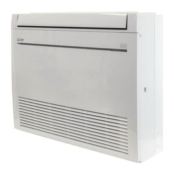
Mitsubishi Electric MUFZ-KJ-NAHZ Series Service Manual

Mitsubishi Electric MUFZ-KJ-NAHZ Series Service Manual

Split-type air conditioners, indoor/outdoor unit

Advertisement

INDOOR UNIT
INDOOR UNIT
SERVICE MANUAL
Models
MFZ-KJ09NA
MFZ-KJ12NA
MFZ-KJ15NA
MFZ-KJ18NA
NOTE:
• This service manual describes technical data of the indoor units.
• RoHS compliant products have <G> mark on the spec name plate.
For servicing of RoHS compliant products, refer to the RoHS Parts List.
-
U1
-
U1
-
U1
-
U1
CONTENTS
1. TECHNICAL CHANGES ··································· 3
2. PART NAMES AND FUNCTIONS ····················· 4
3. SPECIFICATION ················································ 5
4. OUTLINES AND DIMENSIONS ························ 7
5. WIRING DIAGRAM ············································ 8
6. REFRIGERANT SYSTEM DIAGRAM ··············· 9
7. SERVICE FUNCTIONS ··································· 10
8. MICROPROCESSOR CONTROL ··················· 12
9. TROUBLESHOOTING ····································· 21
10. DISASSEMBLY INSTRUCTIONS ···················· 36
PARTS CATALOG (OBB752)
Revision B:
• 4. OUTLINES AND DIMENSIONS has been
modified.
OBH752 REVISED EDITION-A is void.
No. OBH752
REVISED EDITION-B
Outdoor unit service manual
MUFZ-KJ•NAHZ Series (OBH753)
MXZ-C•NA, MXZ-C•NAHZ Series
(OBH702, OCH573)

Advertisement

Table of Contents
loading

Summary of Contents for Mitsubishi Electric MUFZ-KJ-NAHZ Series

  • Page 1: Table Of Contents

    Revision B: • 4. OUTLINES AND DIMENSIONS has been modified. OBH752 REVISED EDITION-A is void. INDOOR UNIT INDOOR UNIT No. OBH752 REVISED EDITION-B SERVICE MANUAL Models MFZ-KJ09NA MFZ-KJ12NA MFZ-KJ15NA MFZ-KJ18NA Outdoor unit service manual MUFZ-KJ•NAHZ Series (OBH753) MXZ-C•NA, MXZ-C•NAHZ Series (OBH702, OCH573) CONTENTS 1.
  • Page 2 Use the speci ed refrigerant only Never use any refrigerant other than that specified. Doing so may cause a burst, an explosion, or fire when the unit is being used, serviced, or disposed of. Correct refrigerant is specified in the manuals and on the spec labels provided with our products. We will not be held responsible for mechanical failure, system malfunction, unit breakdown or accidents caused by failure to follow the instructions.
  • Page 3: Technical Changes

    TECHNICAL CHANGES MFZ-KJ09NA- MFZ-KJ12NA- MFZ-KJ15NA- MFZ-KJ18NA- 1. New model...
  • Page 4: Part Names And Functions

    PART NAMES AND FUNCTIONS MFZ-KJ09NA MFZ-KJ12NA MFZ-KJ15NA MFZ-KJ18NA Horizontal vane Air outlet Vertical vane Fan guard (Anti-allergy enzyme filter, option) Panel Front panel Display and operation section (When the front panel is opened) Emergency operation switch Remote control receiving section Operation indicator lamp ACCESSORIES MFZ-KJ09NA MFZ-KJ12NA...
  • Page 5: Specification

    SPECIFICATION 1. Single connection Indoor model MFZ-KJ09NA MFZ-KJ12NA MFZ-KJ15NA MFZ-KJ18NA Power supply V, phase, Hz 208/230, 1, 60 Max. fuse size (time delay)/ Disconnect switch A COOL Dry 417 - 360 - 272 - 198 - 138 431 - 392 - 311 - 254 - 198 491 - 420 - 328 - 254 - 198 Air ow (Wet)
  • Page 6 3-1. OPERATING RANGE (1) POWER SUPPLY Rated voltage Guaranteed voltage (V) 208/230 V Min. 187 Max. 253 Indoor unit 1 phase 60 Hz (2) OPERATION Intake air temperature (°F) Mode Condition Indoor Outdoor Standard temperature — Maximum temperature — Cooling Minimum temperature —...
  • Page 7: Outlines And Dimensions

    OUTLINES AND DIMENSIONS Unit: inch MFZ-KJ09NA MFZ-KJ12NA MFZ-KJ15NA MFZ-KJ18NA...
  • Page 8: Wiring Diagram

    WIRING DIAGRAM MFZ-KJ09NA MFZ-KJ12NA MFZ-KJ15NA MFZ-KJ18NA...
  • Page 9: Refrigerant System Diagram

    REFRIGERANT SYSTEM DIAGRAM MFZ-KJ09NA MFZ-KJ12NA MFZ-KJ15NA MFZ-KJ18NA Unit: inch (mm) Refrigerant pipe 3/8 ( 9.52) (MFZ-KJ09/12) 1/2 ( 12.7) (MFZ-KJ15/18) (with heat insulator) Indoor heat exchanger Flared connection Distributor Indoor coil thermistor RT12, RT14, RT15 (main) RT13 (sub) Room temperature thermistor RT11 Flared connection...
  • Page 10: Service Functions

    SERVICE FUNCTIONS MFZ-KJ09NA MFZ-KJ12NA MFZ-KJ15NA MFZ-KJ18NA 7-1. TIMER SHORT MODE • For service, the following set time can be shortened by bridging the timer short mode point on the electronic control P.C. board. (Refer to 9-7.) • The set time for the ON/OFF timer can be reduced to 1 second for each minute. •...
  • Page 11 7-3. AUTO RESTART FUNCTION When the indoor unit is controlled with the remote controller, the operation mode, the set temperature, and the fan speed are memorized by the indoor electronic control P.C. board. “AUTO RESTART FUNCTION” automatically starts operation in the same mode just before the shutoff of the main power. Operation If the main power has been cut, the operation settings remain.
  • Page 12: Microprocessor Control

    MICROPROCESSOR CONTROL MFZ-KJ09NA MFZ-KJ12NA MFZ-KJ15NA MFZ-KJ18NA WIRELESS REMOTE CONTROLLER Signal transmitting section Distance of signal : About 20 ft. (6 m) Beep(s) is (are) heard from the indoor unit when the signal is received. FAN SPEED CONTROL button OPERATION SELECT button POWERFUL button ECONO COOL button Operation display section...
  • Page 13 8-1. COOL ( ) OPERATION (1) Press STOP/OPERATE (OFF/ON) button. OPERATION INDICATOR lamp of the indoor unit turns on with a beep tone. (2) Select COOL mode with OPERATION SELECT button. (3) Press TEMPERATURE buttons TEMP button to select the desired temperature. The setting range is 61 - 88°F (16 - 31°C).
  • Page 14 8-5. AUTO CHANGE OVER ··· AUTO MODE OPERATION Once desired temperature is set, unit operation is switched automatically between COOL and HEAT operation. 1. Mode selection (1) Initial mode At first indoor unit operates only indoor fan with outdoor unit OFF for 3 minutes to detect present room temperature. Following the conditions below, operation mode is selected.
  • Page 15 The multi-flow vane is automatically set to the appropriate position. In HEAT, the multi-flow vane automatically changes its position according to the indoor fan speed. Even if 2 FLOW is selected, air will blow only from the top of the unit in the following conditions: •...
  • Page 16 (11) POWERFUL ( ) operation The air conditioner automatically adjusts the fan speed and the set temperature, and operates the POWERFUL mode. The POWERFUL mode is cancelled automatically 15 minutes after operation starts, or when POWERFUL button is pressed once again within 15 minutes after operation starts. The operation mode returns to the mode prior to POWERFUL operation.
  • Page 17 8-8. WEEKLY TIMER OPERATION • A maximum of 4 ON or OFF timers can be set for individual days of the week. • A maximum of 28 ON or OFF timers can be set for a week. E.g. : Runs at 75°F (24°C) from waking up to leaving home, and runs at 81°F (27°C) from getting home to going to bed on weekdays.
  • Page 18 (4) Press button to complete and transmit the weekly timer setting. which was blink- ing goes out, and the current time will be displayed. NOTE: • Press button to transmit the setting information of weekly timer to the indoor unit. Point the remote controller toward the indoor unit for 3 seconds.
  • Page 19 Set temperature for SLEEP operation. For about 30 minutes after SLEEP ( ) button is pressed, the set temperature remains as set for the operation running when the SLEEP button is pressed. It will change to the set temperature for SLEEP operation in about 30 minutes. Pressing SLEEP ( ) button again returns the operation to the previous settings.
  • Page 20 8-11. EMERGENCY/TEST OPERATION Operation mode COOL/HEAT In the case of test run operation or emergency operation, use Set temperature 75°F (24°C) EMERGENCY OPERATION switch on the right side of the indoor unit. Fan speed Medium Emergency operation is available when the remote controller is missing Horizontal vane Auto or has failed, or when the batteries in the remote controller are running...
  • Page 21: Troubleshooting

    TROUBLESHOOTING MFZ-KJ09NA MFZ-KJ12NA MFZ-KJ15NA MFZ-KJ18NA 9-1. CAUTIONS ON TROUBLESHOOTING 1. Before troubleshooting, check the following 1) Check the power supply voltage. 2) Check the indoor/outdoor connecting wire for miswiring. 2. Take care of the following during servicing 1) Before servicing the air conditioner, be sure to turn OFF the main unit first with the remote controller, and then after confirming the horizontal vane is closed, turn OFF the breaker.
  • Page 22 5. Description of multi system air conditioner OUTDOOR UNIT: MXZ series The multi system outdoor unit can be connected to 2 or more indoor units. • The units do not operate and the operation indicator lamp flashes as shown in the figure below when the total capacity of the indoor units exceed the capacity of the outdoor unit.
  • Page 23 9-2. FAILURE MODE RECALL FUNCTION Outline of the function This air conditioner can memorize the abnormal condition which has occurred once. Even though OPERATION INDICATOR lamp indication listed on the troubleshooting check table (9-4.) disappears, the memorized failure details can be recalled. This mode is very useful when the unit needs to be repaired for the abnormality which does not recur.
  • Page 24 2. Indoor unit failure mode table NOTE: Blinking patterns of this mode differs from the ones of Troubleshooting check table (9-4.). Left lamp of Right lamp of Abnormal point OPERATION OPERATION Condition Remedy (Failure mode) INDICATOR lamp INDICATOR lamp Not lighted Not lighted Normal –...
  • Page 25 9-3. INSTRUCTION OF TROUBLESHOOTING Start Indoor unit Indoor unit does Indoor unit operates. OPERATION INDICATOR operates. not receive Outdoor unit does lamp on the indoor unit is Outdoor unit the signal from not operate normally. flashing ON and OFF. does not remote controller.
  • Page 26 9-4. TROUBLESHOOTING CHECK TABLE Before taking measures, make sure that the symptom reappears for accurate troubleshooting. When the indoor unit has started operation and detected an abnormality of the following condition (the first detection after the power ON), the indoor fan motor turns OFF and OPERATION INDICATOR lamp flashes. OPERATION INDICATOR Lighted Blinking...
  • Page 27 OPERATION INDICATOR Lighted Blinking Not lighted Abnormal Operation indicator lamp Symptom Condition Remedy point Right lamp flash When the operation mode of the each indoor Outdoor unit MXZ type • Select the same operation mode unit is differently set to COOL (includes DRY) operates but Operation for all the units.
  • Page 28 9-6. TROUBLESHOOTING FLOW A Check of indoor fan motor The indoor fan motor error has occurred, and the indoor fan does not operate. Turn OFF the power supply. Pay enough attention to the high voltage on the fan motor connector. Turn ON the power supply, wait 5 seconds or more, and then press EMERGENCY OPERATION switch.
  • Page 29 Check of remote controller, display receiver P.C. board and indoor control P.C. board Check if the remote controller is exclusive for this air conditioner. Press STOP/OPERATE (OFF/ON) 1 Look at the image of the signal transmitting section of button on the remote controller. the remote controller through the monitor of a digital camera or a camera phone.
  • Page 30 Check of indoor electronic control P.C. board and indoor fan motor Turn OFF the power supply. Remove indoor fan motor connector CN211 Measure the resistance of indoor fan and vane motor connector CN151 from the Short circuit: motor. indoor electronic control P.C. board and turn Replace the indoor fan motor.
  • Page 31 How to check miswiring and serial signal error MUFZ Type Turn OFF the power supply. Is there rated voltage in the power supply? Check the power supply. Turn ON the power supply. Check the wiring. Is there rated voltage between the outdoor terminal block S1 and S2? Press EMERGENCY OPERATION switch once.
  • Page 32 MXZ Type Turn OFF the power supply. Is there rated voltage in the power supply? Check the power supply. Turn ON the power supply. Is there rated voltage between outdoor terminal block S1 and S2? Check the wiring. Press EMERGENCY OPERATION switch once. Does the left lamp of the OPERATION INDICATOR lamp light up? <Con rmation of the power to the indoor unit>...
  • Page 33 LED indication for communication status Turn ON the power supply. Communication status is indicated by the LED. Unit status Blinking: normal communication Lighting: abnormal communication or Does the LED on the outdoor control P.C. Replace the outdoor control P.C. board. not connected board repeat "3.6-second-OFF Pattern 1 and 2 is repeatedly displayed...
  • Page 34 E Electromagnetic noise enters into TV sets or radios Is the unit grounded? Ground the unit. Is the distance between the antennas Extend the distance between the antennas and and the indoor unit within 9.91 ft. (3m), the indoor unit, and/or the antennas and the or is the distance between the antennas outdoor unit.
  • Page 35 9-7. TEST POINT DIAGRAM AND VOLTAGE MFZ-KJ09NA MFZ-KJ12NA MFZ-KJ15NA MFZ-KJ18NA FUSE (F11) T3.15AL250V Indoor electronic control P.C. board Varistor (NR11) Serial signal input (CN202) JR05 Modification JR06 point for Power supply (CN201) individual input 208/230 VAC operation (Refer to 7-2.) To disable "Auto Resistor restart function",...
  • Page 36: Disassembly Instructions

    DISASSEMBLY INSTRUCTIONS <"Terminal with locking mechanism" Detaching points> The terminal which has the locking mechanism can be detached as shown below. There are 2 types (refer to (1) and (2)) of the terminal with locking mechanism. The terminal without locking mechanism can be detached by pulling it out. Check the shape of the terminal before detaching.
  • Page 37 OPERATING PROCEDURE PHOTOS 3. Removing the electronic control P.C. board and Photo 4 the display receiver P.C. board (1) Remove the panel. (Refer to 1.) (2) Remove the electrical box. (Refer to 2.) (3) Remove the earth wire connected to the electronic control P.C.
  • Page 38 How to remove the multi-flow Horizontal vane (back) vane and the horizontal vanes Horizontal vane (front) Unit body (1) Removing the horizontal vane (front/back) (1)-1. See the figure below and push to open the indicated Multi-flow vane places on the horizontal vanes (between front and back) with your fingers so that you can access 4 vane shafts positioned on the back of the horizontal vanes.
  • Page 39 OPERATING PROCEDURE PHOTOS Photo 9 5. Removing the horizontal vane motor Screws of the nozzle (1) Remove the panel. (Refer to 1.) (2) Remove the screws of the horizontal vane motor sup- port and pull out the horizontal vane motor support from the nozzle.
  • Page 40 OPERATING PROCEDURE PHOTOS 7. Removing the line flow fan and the indoor fan Photo 13 Screw of the line flow fan motor (1) Remove the panel. (Refer to 1.) (2) Remove the electrical box. (Refer to 2.) (3) Remove the nozzle. (Refer to 4.) (4) Disengage the water cover from the catches.
  • Page 42 HEAD OFFICE: TOKYO BLDG., 2-7-3, MARUNOUCHI, CHIYODA-KU, TOKYO 100-8310, JAPAN © Copyright 2016 MITSUBISHI ELECTRIC CORPORATION Issued: May 2017. No. OBH752 REVISED EDITION-B Issued: Mar. 2016. No. OBH752 REVISED EDITION-A Published: Feb. 2016. No. OBH752 Specifications are subject to change without notice.

Table of Contents