Table of Contents
Advertisement
Quick Links
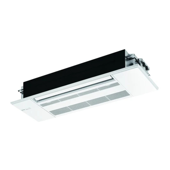
INDOOR UNIT
SERVICE MANUAL
Models
MLZ-KP09NA
MLZ-KP12NA
MLZ-KP18NA
NOTE:
RoHS compliant products have <G> mark on the spec name plate.
-
U1
-
U1
-
U1
CONTENTS
1. TECHNICAL CHANGES ······························2
2. PART NAMES AND FUNCTIONS··················3
3. SPECIFICATION ········································4
4. OUTLINES AND DIMENSIONS ·····················6
5. WIRING DIAGRAM ·····································7
6. REFRIGERANT SYSTEM DIAGRAM ·············8
7. SERVICE FUNCTIONS ································9
8. MICROPROCESSOR CONTROL ················ 12
9. TROUBLESHOOTING ······························· 21
10. DISASSEMBLY INSTRUCTIONS ················ 35
PARTS CATALOG (OBB802)
No. OBH802
Outdoor unit service manual
MXZ-C NA, MXZ-C NAHZ Series
(OBH702, OCH573)
Advertisement
Table of Contents

Subscribe to Our Youtube Channel
Related Manuals for Mitsubishi Electric MXZ-C NA Series


Summary of Contents for Mitsubishi Electric MXZ-C NA Series
-
Page 1: Table Of Contents
INDOOR UNIT No. OBH802 SERVICE MANUAL Models MLZ-KP09NA MLZ-KP12NA MLZ-KP18NA Outdoor unit service manual MXZ-C NA, MXZ-C NAHZ Series (OBH702, OCH573) CONTENTS 1. TECHNICAL CHANGES ······························2 2. PART NAMES AND FUNCTIONS··················3 3. SPECIFICATION ········································4 MLZ-KP09NA 4. OUTLINES AND DIMENSIONS ·····················6 MLZ-KP12NA 5. -
Page 2: Technical Changes
Use the specified refrigerant only Never use any refrigerant other than that specified. Doing so may cause a burst, an explosion, or fire when the unit is being used, serviced, or disposed of. Correct refrigerant is specified in the manuals and on the spec labels provided with our products. We will not be held responsible for mechanical failure, system malfunction, unit breakdown or accidents caused by failure to follow the instructions. -
Page 3: Part Names And Functions
PART NAMES AND FUNCTIONS INDOOR UNIT MLZ-KP09NA MLZ-KP12NA MLZ-KP18NA Horizontal vane Vertical vane Air inlet Intake grille Air outlet (Anti-Allergy Enzyme Display section Spec name plate Safety strings Open the display cover Remote control receiving section Emergency operation switch Operation indicator lamp ACCESSORIES MODELS MLZ-KP09NA MLZ-KP12NA MLZ-KP18NA... -
Page 4: Mlz-Kp09Na
SPECIFICATION 1. Multi connection Indoor model MLZ-KP09NA MLZ-KP12NA MLZ-KP18NA Power supply V, phase, Hz 208/230, 1, 60 Max. fuse size (time delay)/ Disconnect switch A COOL Dry 311 - 283 - 254 - 212 332 - 297 - 258 - 212 403 - 346 - 293 - 212 Airfl... - Page 5 3-1. OPERATING RANGE (1) POWER SUPPLY Rated voltage Guaranteed voltage (V) 208/230 V Min. 187 Max. 253 Indoor unit 1 phase 60 Hz (2) OPERATION *The operating range of the outdoor unit depends on the connected outdoor unit. Intake air temperature (°F) Mode Condition Indoor...
-
Page 6: Outlines And Dimensions
OUTLINES AND DIMENSIONS MLZ-KP09NA MLZ-KP12NA MLZ-KP18NA Unit: inch INDOOR UNIT OBH802... -
Page 7: Mlz-Kp18Na 5. Wiring Diagram
WIRING DIAGRAM INDOOR UNIT MLZ-KP09NA- MLZ-KP12NA- MLZ-KP18NA- OBH802... -
Page 8: Refrigerant System Diagram
REFRIGERANT SYSTEM DIAGRAM INDOOR UNIT MLZ-KP09NA MLZ-KP18NA Unit: inch(mm) MLZ-KP12NA Refrigerant pipe Ø3/8(Ø9.52) Refrigerant pipe Ø1/2(Ø12.7) (with heat insulator) (with heat insulator) Indoor coil Indoor coil thermistor thermistor Indoor Indoor RT12,RT14, heat heat RT12 (main) RT15 (main) exchanger exchanger Flared connection Flared connection Indoor coil Indoor coil... -
Page 9: Service Functions
SERVICE FUNCTIONS MLZ-KP09NA MLZ-KP12NA MLZ-KP18NA 7-1. TIMER SHORT MODE • For service, the following set time can be shortened by bridging the timer short mode point on the electronic control P.C. board. (Refer to 10-7.) • The set time for the ON/OFF timer can be reduced to 1 second for each minute. •... - Page 10 7-3. AUTO RESTART FUNCTION When the indoor unit is controlled with the remote controller, the operation mode, the set temperature, and the fan speed are memorized by the indoor electronic control P.C. board. “AUTO RESTART FUNCTION” automatically starts operation in the same mode just before the shutoff of the main power. Operation If the main power has been cut, the operation settings remain.
- Page 11 7-4. P.C. BOARD MODIFICATION FOR CHANGING AIRFLOW VOLUME Change dip switch SW3 setting according to the height of ceiling. Dip switch SW3 Normal Increase airflow volume Ceiling height 8.0 ft. (2.4 m) or below above 8.0 ft. (2.4 m) and 9.0 ft. (2.7 m) or below NOTE: When the ceiling is above 9.0 ft.
-
Page 12: Microprocessor Control
MICROPROCESSOR CONTROL MLZ-KP09NA MLZ-KP12NA MLZ-KP18NA WIRELESS REMOTE CONTROLLER Signal transmitting section Operate the remote control- Distance of signal: About 20 ft. (6 m) ler in the area where signal is Beep(s) is (are) heard from received, and beep is heard. the indoor unit when the signal is received.
Need help?
Do you have a question about the MXZ-C NA Series and is the answer not in the manual?
Questions and answers