Advertisement
Quick Links
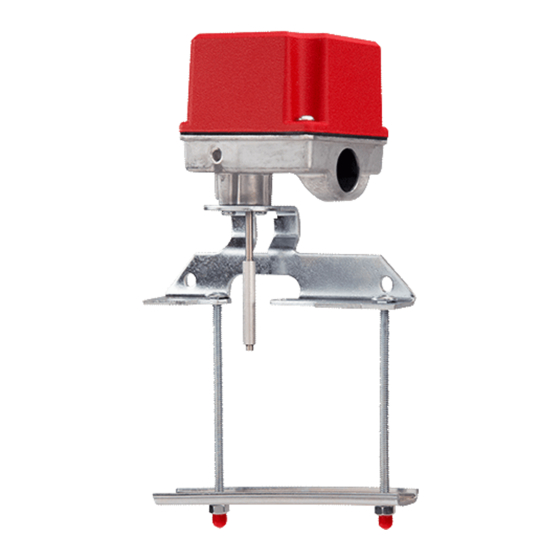
INSTALLATION AND MAINTENANCE INSTRUCTIONS
OSY2 Gate Valve
Supervisory Switch
Specifications
Contact Ratings:
Dimensions:
Maximum Stem Extension:
Minimum Stem Extension:
Bracket Span:
Operating Temperature Range:
Shipping Weight:
Enclosure Rating:
Important
Please Read Carefully And Save
This instruction manual contains important information on
the installation and operation of supervisory switches.
Purchasers who install supervisory switches for use by oth-
ers must leave this manual or a copy of it with the user.
These instructions apply to System Sensor switches for out-
side screw and yoke valves only. Read all instructions
carefully before beginning installation.
Do NOT use this switch in explosive or potentially explo-
sive atmospheres.
Do NOT leave unused wires exposed.
All supervisory switch installations must comply with local
codes and ordinances and the requirements of the authority
having jurisdiction. Additional information is available in
National Fire Protection Association standards NFPA 13,
13D, 13R, 71, and 72.
General Installation Considerations
The OSY2 Supervisory Switch can be mounted on open
yoke valves between
tions shown in Figure 1 only. If the switch is installed with
the actuator pointing upward, water may leak into the inte-
rior of the switch. Therefore, do NOT install the OSY2
with its actuating lever pointing upward.
All OSY2 models are equipped with a ground screw inside
the switch housing near the conduit exit hole for those ap-
plications where grounding is required.
N770-04-00
Technical Manuals Online! - http://www.tech-man.com
10 A @ 125/250 VAC
2.5 A @ 24 VDC
3
1
5
/
"H X 3
/
4
2
2
5
/
"
8
5
/
"
8
6
3
/
"
4
32° - 120° F (0° C - 49° C)
3
2
/
lb.
4
NEMA Type 3R when mounted with the actuator vertical (cover on top) as tested by
Underwriters Laboratories, Inc.
WARNING
1
/
" and 12" in diameter in the posi-
2
1
"W X 3
/
"L
4
Figure 1:
ACTUATOR
VERTICAL
Narrow Yoke Valves
As Figure 2 suggests, installing the valve with mounting
bolts inside the yoke is recommended. However, some
valves may have yokes that are too narrow for this arrange-
ment. If this is the case, the bolts can be positioned on the
outside of the yoke.
Limited Clearance Valves
The OSY2 mounting bracket fits most of the open yoke
valves used in fire protection systems. However, some of
these valves, especially those less than 1
have irregularly shaped yokes or such limited clearances
that the clamping bar cannot be installed properly and/or it
causes the valve to bind. If this is the case, the use of the
supplied J-bolts is required to attach the OSY2 to the valve
(see J-Bolt Detail, Figure 2).
Installation Instructions
See Figures 2 and 3, as required, while performing the pro-
cedure that follows.
Perform step 1 on valves 1
only. Proceed directly to step 2 if the switch is being in-
stalled on a valve larger than 1
1
A Division of Pittway
3825 Ohio Avenue, St. Charles, Illinois 60174
1-800-SENSOR2, FAX: 630-377-6495
ACTUATOR
HORIZONTAL
1
/
" in diameter,
2
1
/
" in diameter and smaller
2
1
/
" in diameter.
2
I56-393-06
Advertisement

Related Manuals for System Sensor OSY2


Summary of Contents for System Sensor OSY2
- Page 1 If this is the case, the use of the yoke valves between " and 12" in diameter in the posi- supplied J-bolts is required to attach the OSY2 to the valve tions shown in Figure 1 only. If the switch is installed with (see J-Bolt Detail, Figure 2).
- Page 2 Figure 2: Wrench for Cover tamper-resistant screws Tamper-resistant (P/N WFDW) screws Spring Actuating Cam Mounting screws Actuating lever set screw Terminal block Seal Base housing Mounting Bracket "C" clip Actuating lever roller (2 thru 12"only) Valve Stem Carriage Bolt Yoke Clamping Bar Hex wrench Retaining Washer...
- Page 3 (COM to B circuit 2. Set the valve to its fully open position. Remove the OSY2 open) when the actuating lever is in the groove with Supervisory Switch from the carton and adjust the posi- the valve in the full open position.
- Page 4 60174. Please include a note describing the malfunction and suspected period of three years from date of manufacture. System Sensor makes no cause of failure. The Company shall not be obligated to repair or replace other express warranty for this supervisory switch.
Need help?
Do you have a question about the OSY2 and is the answer not in the manual?
Questions and answers