Advertisement
Quick Links
INSTALLATION AND MAINTENANCE INSTRUCTIONS
EPS40EXP and EPS120EXP Explosion Proof
Supervisory Pressure Switches
Specifications
Contact Ratings:
Operating Temperature Range:
Maximum Service Pressure (in PSI): 250
Adjustment Range:
Approximate Differential:
Enclosure Rating:
Hazardous Atmospheres
Classification:
Important
Please Read Carefully and Save
This instruction manual contains important information
about the installation and operation of supervisory pres-
sure switches. Purchasers who install switches for use by
others must leave this manual or a copy of it with the user.
Read all instructions carefully before installation, following
only those instructions that apply to the model you are
installing.
Before installing any alarm device, be thoroughly familiar
with:
NFPA 72:
National Fire Alarm Code
NFPA 13:
Installation of Sprinkler Systems
NFPA 25:
Inspection, Testing, and Maintenance of Water-
based Fire Protection Systems
Other applicable NFPA standards, local codes, and the
requirements of the authority having jurisdiction.
Failure to follow these directions may result in failure of the
device to report an alarm condition. System Sensor is not
responsible for devices that have been improperly installed,
tested, or maintained.
D770-26-00
10 A, 1/2 HP @ 125/250 VAC
2.5A @ 6/12/24 VDC
–40°F to +160°F
EPS40EXP
EPS120EXP
250
10-100
10-200
3 PSI @ 10 PSI
3 PSI @ 10 PSI
8 PSI @ 100 PSI
9 PSI @ 200 PSI
NEMA Type 4 — Indoor/Outdoor use
Class I, Groups B, C, D, Div. 1
Class II, Groups E, F, G, Div. 1
Class III, Div. 1
Operation
As pressure changes, a diaphragm actuates 2 snap action
switches. The pressure switch actuation is determined by
adjustment settings.
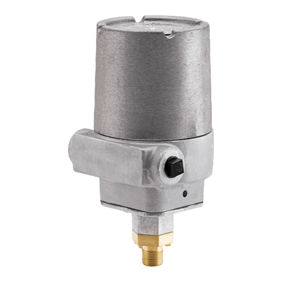
Figure 1. Pressure switch basic dimensions:
COVER
1
firealarmresources.com
3825 Ohio Avenue, St. Charles, Illinois 60174
1-800-SENSOR2, FAX: 630-377-6495
4.9"
LOCKING
SCREW
www.systemsensor.com
HEX ADJUST
SCREW
1/4" HEX HEAD
COVER
TAMPER
SET SCREW
(WRENCH
PROVIDED)
ADJUSTMENT
WHEEL
9.5"
COVER
(WRENCH
PROVIDED)
MAIN ADJUSTMENT
WHEEL (TURN
COUNTERCLOSKWISE
TO INCREASE
PRESSURE)
1/2" NPT
I56-1428-001R
Advertisement

Related Manuals for System Sensor EPS40EXP


Summary of Contents for System Sensor EPS40EXP
- Page 1 COVER (WRENCH PROVIDED) Failure to follow these directions may result in failure of the device to report an alarm condition. System Sensor is not responsible for devices that have been improperly installed, tested, or maintained. MAIN ADJUSTMENT LOCKING...
- Page 2 Figure 2. Typical piping diagram for EPS40EXP Figure 3. Typical piping diagram for EPS120EXP WIRE TO SUPERVISORY WIRE TO ALARM CIRCUIT OF FIRE ALARM INDICATING CIRCUIT EPS120EXP PRESSURE CONTROL PANEL OF FIRE ALARM EPS40EXP EPS10EXP CONTROL PANEL SUPPLY SPRINKLER SYSTEM...
- Page 3 Each tine on the wheel represents an approximate win- testing as required by the applicable NFPA standards dow shift of 1.8 PSI for the EPS40EXP and 6.6 PSI for the but not less than bi-monthly. EPS 120EXP. For each 1/2 rotation of the adjustment wheel, the window changes by approximately 11 PSI for •...
- Page 4 Please include a note describing the malfunction and suspected cause of period of three years from date of manufacture. System Sensor makes no failure. The Company shall not be obligated to repair or replace units other express warranty for this pressure switch.
Need help?
Do you have a question about the EPS40EXP and is the answer not in the manual?
Questions and answers