Advertisement
Quick Links
INSTALLATION AND MAINTENANCE INSTRUCTIONS
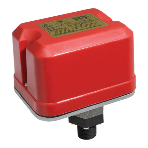
EPS10 Series Alarm Pressure Switches
SPECIFICATIONS
Contact Ratings:
Overall Dimensions:
Operating Temperature Range:
Maximum Service Pressure:
Maximum Adjustment Range:
Enclosure Rating:
Approximate Differential:
FIGURE 1. PRESSURE SWITCH BASIC DIMENSIONS:
4-1/4"
GROUND
SCREW
(GREEN)
5-1/8"
LOCKING SCREW
IMPORTANT
Please Read Carefully and Save
This instruction manual contains important information about the installation
and operation of alarm pressure switches. Purchasers who install switches for
use by others must leave this manual or a copy of it with the user.
Read all instructions carefully before installation, following only those instruc-
tions that apply to the model you are installing.
Before installing any alarm device, be thoroughly familiar with:
NFPA 72:
Installation, Maintenance, and Use of Protective Signaling Systems
NFPA 13:
Installation of Sprinkler Systems
NFPA 13A: Inspection, Testing, and Maintenance of Sprinkler Systems
Other applicable NFPA standards, local codes, and the requirements of the
authority having jurisdiction.
Failure to follow these directions may result in failure of the device to report
an alarm condition. System Sensor is not responsible for devices that have
been improperly installed, tested, or maintained.
CAUTION
Do not use in potentially explosive atmospheres.Do not leave unused wires exposed.
D770-08-00
10 A,
1
/
HP @ 125/250 VAC
2
8 A, 125/250 VAC (LPCB only)
2.5A @ 6/12/24 VDC
See Figure 1
–40° to +160°F
300 PSI
4 – 20 PSI
UL 4x — Indoor or Outdoor Use
NEMA 4 — Indoor or Outdoor Use
IP54
3 PSI throughout range
HEX
SWITCH #2
ADJUSTMENT
SCREW
MAIN ADJUSTMENT
WHEEL
1/2" NPT
W0170-00
firealarmresources.com
3825 Ohio Avenue, St. Charles, Illinois 60174
OPERATION
As pressure changes, a diaphragm actuates 1 or 2 snap action switches. The
pressure switch actuation is determined by adjustment settings.
INSTALLATION
1.
Remove Cover
Cover is held on by two tamper resistant screws. (Removal key is en-
closed with pressure switch.)
2.
Mounting the Switch
The device is designed to be mounted in the upright or horizontal posi-
tion; side mounting is also acceptable. Locate it where vibration, shock,
and mechanical loading are minimal. Refer to piping diagram (Figure 2
on page 2).
a. Mount the device directly to the line via the
nection. The use of teflon pipe sealant tape is recommended. Be
sure the fitting is tight enough to prevent leaks.
b. Apply tightening torque to the black plastic hex portion of device.
High voltage. Electrocution hazard. Do not handle live AC wiring or work on
a device to which AC power is applied. Doing so may result in severe injury
or death. When utilizing switches at voltages greater than 74 VDC
49 VAC
, means to provide all-pole disconnection must be incorporated in
the field wiring, such as a circuit breaker.
3.
Wire the device in accordance with the National Electrical Code. Two
7
⁄
" diameter conduit connection holes have been provided in the
8
mounting plate to accept standard
able knock-out type). If a NEMA 4/UL 4x (waterproof unit) is re-
quired, waterproof flexible metallic conduit and appropriate conduit
fittings must be used. Recommended connectors are Thomas and
Betts PN 5332 (180° coupling), PN 5352 (90° coupling), and PN 5262
seal ring.
4.
Connect wiring to terminals (see Figure 3 and Table 1).
TABLE 1. ELECTRICAL CONNECTIONS
(REFERENCED AT FACTORY SETTINGS):
MODEL EPS10-1
SWITCH AT 0 P.S.I.
B
COM
A
SWITCH AT 4-8 P.S.I. (HIGH TRIP PT.)
B
COM
A
SWITCH 1
1
1-800-SENSOR2, FAX: 630-377-6495
www.systemsensor.com
1
⁄
" NPT pressure con-
2
WARNING
1
⁄
" conduit fittings (one is remov-
2
MODEL EPS10-2
SWITCHES AT 0 P.S.I.
B
B
COM
COM
A
A
SW1
SW2
SWITCHES AT 4-8 P.S.I. (HIGH TRIP PT.)
B
B
COM
COM
A
A
SW1
SW2
BOTH SWITCHES ACTIVATE SIMULTANEOUSLY
I56-0551-009R
or
Advertisement

Subscribe to Our Youtube Channel
Related Manuals for System Sensor EPS10 Series


Summary of Contents for System Sensor EPS10 Series
- Page 1 SWITCHES AT 0 P.S.I. Failure to follow these directions may result in failure of the device to report an alarm condition. System Sensor is not responsible for devices that have been improperly installed, tested, or maintained. SWITCH AT 4-8 P.S.I. (HIGH TRIP PT.) SWITCHES AT 4-8 P.S.I.
- Page 2 Please refer to insert for the Limitations of Fire Alarm Systems THREE-YEAR LIMITED WARRANTY System Sensor warrants its enclosed pressure switch to be free from defects in materials Department, RA #__________, 3825 Ohio Avenue, St. Charles, IL 60174. Please include a and workmanship under normal use and service for a period of three years from date of note describing the malfunction and suspected cause of failure.
Need help?
Do you have a question about the EPS10 Series and is the answer not in the manual?
Questions and answers