Advertisement
INSTALLATION AND MAINTENANCE INSTRUCTIONS
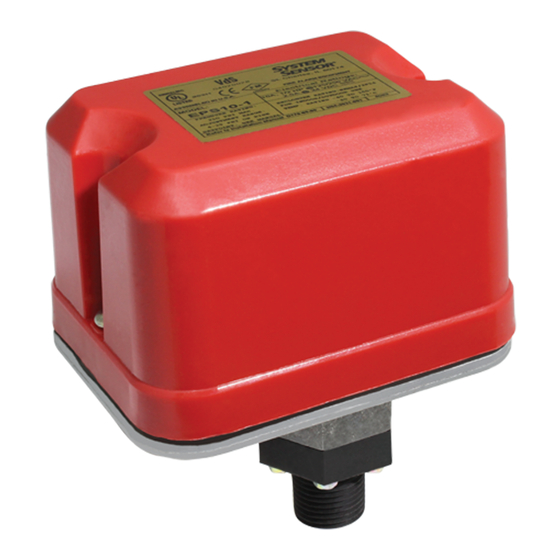
EPS10 Series Alarm
Pressure Switches
Specifications
Contact Ratings:
Overall Dimensions:
Operating Temperature Range:
Maximum Service Pressure:
Maximum Adjustment Range:
Enclosure Rating:
Approximate Differential:
Important
Please Read Carefully and Save
This instruction manual contains important information
about the installation and operation of alarm pressure
switches. Purchasers who install switches for use by others
must leave this manual or a copy of it with the user.
Read all instructions carefully before installation, follow-
ing only those instructions that apply to the model you are
installing.
Before installing any alarm device, be thoroughly familiar
with:
NFPA 72:
Installation, Maintenance, and Use of Protective
Signaling Systems
NFPA 13:
Installation of Sprinkler Systems
NFPA 13A: Inspection, Testing, and Maintenance of
Sprinkler Systems
Other applicable NFPA standards, local codes, and the
requirements of the authority having jurisdiction.
Failure to follow these directions may result in failure of the
device to report an alarm condition. System Sensor is not
responsible for devices that have been improperly installed,
tested, or maintained.
Do not use in potentially explosive atmospheres.
Do not leave unused wires exposed.
D770-08-00
10 A,
1
/
HP @ 125/250 VAC
2
2.5A @ 6/12/24 VDC
See Figure 1
–40° to +160°F
250 PSI
4 – 20 PSI
UL 4x — Indoor or Outdoor Use
NEMA 4 — Indoor or Outdoor Use
IP54
3 PSI throughout range
CAUTION
3825 Ohio Avenue, St. Charles, Illinois 60174
Operation
As pressure changes, a diaphragm actuates 1 or 2 snap
action switches. The pressure switch actuation is deter-
mined by adjustment settings.
Installation
1. Remove Cover
Cover is held on by two tamper resistant screws.
(Removal key is enclosed with pressure switch.)
2. Mounting the Switch
The device is designed to be mounted in the upright or
horizontal position; side mounting is also acceptable.
Locate it where vibration, shock, and mechanical load-
ing are minimal. Refer to piping diagram (Figure 2 on
page 2).
Figure 1. Pressure switch basic dimensions:
GROUND
SCREW
(GREEN)
5-1/8"
LOCKING SCREW
1
1-800-SENSOR2, FAX: 630-377-6495
www.systemsensor.com
4-1/4"
SWITCH #2
HEX
ADJUSTMENT
SCREW
MAIN ADJUSTMENT
WHEEL
1/2" NPT
I56-0551-007R
W0170-00
Advertisement
Table of Contents

Related Manuals for System Sensor EPS10 Series


Summary of Contents for System Sensor EPS10 Series
- Page 1 Other applicable NFPA standards, local codes, and the requirements of the authority having jurisdiction. Failure to follow these directions may result in failure of the SWITCH #2 device to report an alarm condition. System Sensor is not ADJUSTMENT GROUND SCREW...
- Page 2 Figure 2. Typical piping diagram for EPS10-1, EPS10-2 EPS10 EPS10 WIRE TO ALARM WIRE TO ALARM WIRE TO ALARM INDICATING CIRCUIT INDICATING CIRCUIT INDICATING CIRCUIT OF FIRE ALARM EPS10EXP OF FIRE ALARM EPS10EXP OF FIRE ALARM EPS10 CONTROL PANEL CONTROL PANEL CONTROL PANEL WATER SPRINKLER...
- Page 3 If you have any factory to alarm at 4–8 PSI on rising pressure (see Table questions, consult System Sensor. System Sensor 2). Pressure switch settings may be adjusted in the field to recommends careful consideration of the follow-...
- Page 4 The Company shall not be obligated to repair or replace units period of three years from date of manufacture. System Sensor makes no which are found to be defective because of damage, unreasonable use, other express warranty for this pressure switch.
Need help?
Do you have a question about the EPS10 Series and is the answer not in the manual?
Questions and answers