Table of Contents
Advertisement
Advertisement
Table of Contents

Related Manuals for Radionics D8128D

Summary of Contents for Radionics D8128D
- Page 1 D8128D OctoPOPIT Module Installation Instructions...
- Page 2 D8128D OctoPOPIT Module Installation Instructions 41343D Page 2 © 2001 Radionics...
-
Page 3: Table Of Contents
Figure 1: D8128D OctoPOPIT Layout..........................9 Figure 2: Mounting Enclosure............................10 Figure 3: Wiring the D8128D to the Panel with a D8125 POPEX Module............... 12 Figure 4: Wiring the D8128D to the Panel using the Molex Connectors ................. 13 Figure 5: Wiring Multiple D8128Ds using Molex Connectors..................13 Figure 6: D8128D OctoPOPIT Sensor Loops........................ - Page 4 D8128D Contents Notes: D8128D OctoPOPIT Module Installation Instructions 41343D Page 4 © 2001 Radionics...
-
Page 5: Introduction
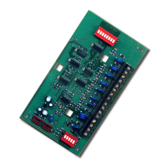
The D8128D OctoPOPIT Module combines the functions of the D8125 POPEX module and the D8127/D9127 POPIT modules to provide eight off-board points in a single module. You can wire both D8128D OctoPOPIT and D8125 POPEX modules in parallel to the ZONEX Bus terminals on the same panel. -
Page 6: Requirements For Fire Initiation Applications
D8128D Introduction applications, such as indicating circuit supervision (using the D192C Bell Circuit Supervision Module), sprinkler supervision, and valve tamper protection. Do not connect fire alarm initiating devices directly to the D8128D. 1.3.1 Requirements for Fire Initiation Applications You must use the D125B Powered Loop Interface Module or D129 Dual Class A initiation Circuit Module for fire initiation applications. -
Page 7: D8128D Overview
Review the Power Outputs section of your panel’s Operation and Installation Manual to be sure you provide enough power for the OctoPOPITs and other powered devices you wish to connect to your system. The D8128D is designed for use with the Radionics’ panels shown in the table below. (Also shown are previously manufactured D8128 OctoPOPIT Modules.) - Page 8 D8128D Overview Notes: D8128D OctoPOPIT Module Installation Instructions 41343D Page 8 © 2001 Radionics...
-
Page 9: Installation
3.1.1.2 Line Termination Switch Settings Switch 5 sets line termination. • If there is no D8125 POPEX module connected to ZONEX 1, set switch 5 of only one D8128D connected to those terminals to the ON position. • If there is a D8125 POPEX module connected to ZONEX 1, set switch 5 of all D8128Ds connected to those terminals to the OFF position. -
Page 10: Mounting The Octopopit
Power down the panel by disconnecting the positive (red) battery lead at the battery and unplugging the transformer. The D8128D can be up to 200 feet (61 meters) away from the Control/Communicator. There are two methods for connecting the D8128D to a Control/Communicator. You can wire the OctoPOPIT to the control/communicator using the terminal strip on the side of the module, or you can connect it using the Molex connectors (P1 and P2). -
Page 11: Connecting The D8128D To The Control/Communicator Using The Terminal Strip
D8128D Installation 3.3.1 Connecting the D8128D to the Control/Communicator using the Terminal Strip When connecting the D8128D to a D9412, D9112, D7412, or D7212 via the OctoPOPIT’s terminal strip the following connections must be made: D8128D D9412/D9112 D8128D D7412/D7212 Common... -
Page 12: Figure 3: Wiring The D8128D To The Panel With A D8125 Popex Module
P O I N T S D8125 POPEX D9127U POSITIVE (+) NEGATIVE (-) ZONE EXPANSION LOOP Figure 3: Wiring the D8128D to the Panel with a D8125 POPEX Module D8128D OctoPOPIT Module Installation Instructions 41343D Page 12 © 2001 Radionics... -
Page 13: Connecting The D8128D To The Control/Communicator Using Molex Connectors
Figure 4: Wiring the D8128D to the Panel using the Molex Connectors When connecting multiple D8128Ds to a control/communicator, you may connect the control/communicator terminals to P1 on the first D8128D and then connect P2 of the first D8128D to P1 of the second D8128D and so Control/Communicator... -
Page 14: Wiring Octopopit Sensor Loops
Each sensor loop is assigned a point number and transmits to the panel separately. Radionics recommends you use twisted-pair wire for the OctoPOPIT sensor loops to avoid EMI problems. Run wires away from the premises telephone and AC wiring. If you suspect a noisy environment, use shielded cable. -
Page 15: D8128D Octopopit Switch Settings For D7412 And D7212
D8128D Installation 3.4.2 D8128D OctoPOPIT Switch Settings for D7412 and D7212 ZONEX 1 D8128D Address Switches Refer to the table at right to set the OctoPOPIT switches Points 9-75 for use with the D7412 and D7212 9-16 Control/Communicators. 17-24 * Line Termination Switch... -
Page 16: Index
D8128D Mounting Enclosure ......... 10 D8128D ..............7 D8128D OctoPOPIT Layout ........9 D8128D OctoPOPIT Sensor Loops ......14 D8128D Wiring to Panel with D8125 POPEX Module ................. 12 Table Wiring multiple OctoPOPITs to Panel with Molex Compatible Control Panels ........7 Connectors ............
Need help?
Do you have a question about the D8128D and is the answer not in the manual?
Questions and answers