Table of Contents
Advertisement
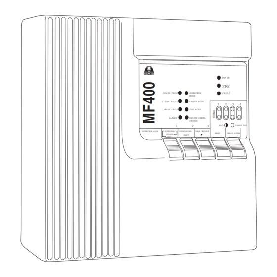
MENVIER FIRE SYSTEM
MF200/400 MF200-72/400-72
For service
please call:
Service agreement number
Cooper Lighting and Security Ltd.
Wheatley Hall Road, Doncaster, South Yorkshire, DN2 4NB, United Kingdom
Sales
Tel:
+44 (0)1302 - 303303
Fax:
+44 (0)1302 - 367155
E-mail: sales@cooper-ls.com
PLEASE PASS THIS BOOKLET TO THE USER,
AFTER INSTALLATION KEEP WITH PANEL.
General
+44 (0)1302 - 321541
+44 (0)1302 - 303220
technical@cooper-ls.com
POW ER FAULT
SUPERVI SOR
M ODE
SYS TEM FAULT
DI SABLE M ODE
EART H FAULT
TEST M ODE
ALAR MS
REM OTE SI GNAL
DI SABLE
1
2
SUPERVI SOR M ODE
SUPERVI SOR
SI LENCE/ SOUND
DI SABLE
SELECT
TEST
Tel:
Export
+44 (0)1302 - 303250
+44 (0)1302 - 303251
export@cooper-ls.com
PINST MF4/V
POW ER
FI RE
FAULT
1
2
3
4
3
FAULT
DI SABLE T EST
LAM P T EST/ EXI T
RESET
SI LENCE BUZZE R
Lighting and Security
www.cooper-ls.com
Advertisement
Table of Contents

Related Manuals for Cooper MENVIER MF200


Summary of Contents for Cooper MENVIER MF200
-
Page 1: Service Support Number
For service Tel: please call: Service agreement number PLEASE PASS THIS BOOKLET TO THE USER, AFTER INSTALLATION KEEP WITH PANEL. Cooper Lighting and Security Ltd. Lighting and Security Wheatley Hall Road, Doncaster, South Yorkshire, DN2 4NB, United Kingdom Sales General Export... -
Page 2: Table Of Contents
CONTENTS SERVICE SUPPORT NUMBER ......................1 SYSTEM INFORMATION ........................2 PANEL CONTROLS AND INDICATORS ....................3 PANEL OPERATION ...........................4 GENERAL ............................ 4 NORMAL OPERATION ........................ 4 SUPERVISOR MODE ........................4 PANEL INTERFACE CONNECTIONS AND PANEL CONTROLS ........... 6 INPUTS ............................6 OUTPUTS ............................ -
Page 3: Panel Controls And Indicators
PANEL CONTROLS AND INDICATORS Visual DESIGNED TO EN54 PART 2&4 1997 DESIGNED TO EN54 PART 2&4 1997 POWER POWER FIRE FIRE SUPERVISOR SUPERVISOR POWER FAULT POWER FAULT FAULT FAULT MODE MODE SYSTEM FAULT SYSTEM FAULT DISABLE MODE DISABLE MODE EARTH FAULT EARTH FAULT TEST MODE TEST MODE... -
Page 4: Panel Operation
PANEL OPERATION General The panel has 2 levels of operation. Normal Mode and Supervisor Mode. Normal Operation Silence Buzzer (key 5) The user can silence the PANEL buzzer by pressing the 'SILENCE BUZZER' key (at any time), the buzzer will then give a beep approximately every 10 seconds. Note:- This does not silence the alarms only the panel buzzer. - Page 5 PANEL OPERATION - continued 2. Release and repress (key 3) to toggle through LED's representing each function. 3. When you highlight the LED representing each function to be enabled/disabled press 'key select’ to enable/disable this function. 4. To exit Disable Mode and leave the panel in the disable state press 'key 1' to toggle to Supervisor Mode LED and press ‘key 3’...
-
Page 6: Panel Interface Connections And Panel Controls
PANEL INTERFACE CONNECTIONS AND INTERFACE CONTROLS Inputs Class Change A pair of terminals are provided for class change. By shorting these terminals together (e.g. switch, time clock) the alarms will sound. The panel will not indicate a fire. The alarms will cancel when the short circuit is removed. -
Page 7: Wiring Diagrams
WIRING DIAGRAMS CABLE SCN CABLE SCN CABLE SCN CABLE SCN CABLE SCN CABLE SCN CABLE SCN CABLE SCN PAGE 7... -
Page 8: Installation Instructions
INSTALLATION INSTRUCTIONS General All cables entering the panel must be via the cable entries provided or the aperture in the rear face. All cables must be tested for earth fault before connecting to the panel. Do not use a High Voltage Tester (Megger) on any cable after connection to any equipment including the panel. -
Page 9: Installing The Panel
INSTALLATION INSTRUCTIONS - continued Installing the Panel Read all the installation instructions before commencing with the installation. Installation of this panel must be done by a suitably qualified/trained person. The installation must comply with IEE wiring regulations and with BS5839 part 1 1988. The electronic components within the Fire Panel are Static Sensitive. -
Page 10: Faults
FAULTS General All fault conditions on the fire panel will be indicated by the 'FAULT' LED flashing, the panel buzzer beeping and at least one other fault specific LED flashing. The auxiliary fault output will de-activate. All faults indications will be cleared automatically if the fault is removed unless stated. CAUTION ELECTRIC SHOCK HAZARD :- BEFORE REMOVING THE PANEL COVER THE MAINS SUPPLY MUST BE TURNED OFF. -
Page 11: Technical Specification
TECHNICAL SPEC Standards Design to comply with EN54 Part 4 1996 and Part 2 1996 Electromagnetic Compatibility EN 50130-4 1996 Alarm Systems Part 4 EN50081-1 1992 EN61000-2-2-1994 Number of Zones 4(MF400) 2(MF200) Number of alarm Lines Mains Input Voltage 240Vac +10%-15% Standby Duration 24Hr System operating Voltage...
Need help?
Do you have a question about the MENVIER MF200 and is the answer not in the manual?
Questions and answers