
Related Manuals for Cooper CFDAU30


Summary of Contents for Cooper CFDAU30
-
Page 1: Voice Alarm System
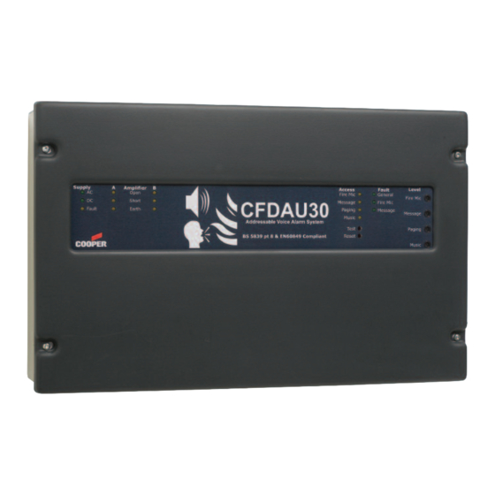
CFDAU30 Voice Alarm System Installation and Maintenance Manual Cooper Lighting and Safety Ltd Wheatley Hall Road Doncaster South Yorkshire DN2 4NB TEL: +44 (0) 1302 321541 FAX: +44 (0) 1302 303220... - Page 2 Cooper has been developed a VA system to replace talking sounders in many voice alarm applications, and is available in several forms. The CFDAU30 is a complete VA system in a single wall mount box which is complete with messages, fire interface, dual 30W monitored amplifiers, power supply, monitored battery charger and the ability to connect non monitored paging and music directly.
-
Page 3: Operation
It is well documented that only 13% of people react to bells, whilst 70% react to a voice message. The CFDAU30 has been developed to draw the minimum of current in standby conditions and mutes the music when the AC supply fails, the unit then draws 60mA quiescent current allowing the use of 3.2AH commodity SLA batteries for full compliance with BS5839 part 8. -
Page 4: Maintenance
investigate the cause of the fault, this should be indicating a Sounder or Voice alarm fault on the Fire Alarm Panel. Maintenance. It is a requirement of BS5839pt8 that a maintenance agreement be in place for Voice Alarm systems, the maintenance schedule should be as follows. Weekly: Broadcast the test message to all zones, and check speaker operation, microphones should be checked for operation if fitted, record results in the site log. -
Page 5: Indications And Controls
Either the AC supply or DC supply is unavailable, or a fuse has ruptured. Amplifier Section Indicators (both channels are identical and independent) Open The CFDAU30 cannot see both end of line resistors for this amplifier channel. Short The CFDAU30 has detected a short on this amplifier channel. -
Page 6: Important Safety Information
Important Safety Information This Equipment must only be installed and maintained by suitably skilled and competent person. This Equipment is defined as Class 1 in EN60065 (Low Voltage Directive) and must be EARTHED. INDOOR USE ONLY AUTION SHOCK HAZARD- ARNING ISOLATE BEFORE OPENING TO REDUCE THE RISK OF FIRE OR ELECTRIC SHOCK, DO NOT EXPOSE THIS... -
Page 7: Unpacking The Unit
Unpacking the Unit Remove the Cooper CFDAU30 from its packing, and check the contents against the following list: Cooper CFDAU30 control Unit. Installation & maintenance manual (this document) Cooper User Guide & logbook. Accessory pack with the following contents:- a. Spare Mains Fuse. - Page 8 Before mounting the CFDAU30 on the wall it is advisable to remove the cable knockouts. Decide how the wiring will be brought into the panel and remove the required knockouts for cable entry.
-
Page 9: Planning The Wiring
Mounting Cooper CFDAU30 Before mounting the CFDAU30 on the wall it is advisable to remove the cable knockouts. Decide the best cable routes from the drawing below: Fire Paging Speaker Speaker Addressable Circuit A Circuit B Loop Interface Safety Board... -
Page 10: Mains Connection
For 72hour standby and 1 hour operation 2 number 12V 17AH batteries are required, these will need to be fitted in an external battery enclosure, the monitored charger in the Cooper CFDAU30 is capable of charging and monitoring these batteries. -
Page 11: Speaker Circuits
The wiring goes through each speaker, and in the last speaker the end of line resistor. Each circuit can have 2 spurs, the CFDAU30 is provided with two end of line resistors per circuit, both must be fitted to avoid faults being shown on the panel. If only one spur is used per circuit, one resistor resides in the panel;... - Page 12 The lines should now be checked for the DC resistance between cores, this should read 9K Ohms if the wires from the CFDAU30 to the end of lines are complete. The speaker lines should also be tested between each core and earth, this should be in excess of 100K Ohms, if not check the cabling, record the results in the user logbook Speaker cables must be earthed to the safety earth connection point (see earlier in this manual);...
- Page 13 The Cooper CFDAU30 is designed to work with the ALFM1 fire microphone, which is connected Pin for Pin as described below: Note in each block the connections are reversed, on the ALFM1 the Au- pin is on the top, on the Cooper CFDAU30 the Au- pin is at the bottom of the block.
- Page 14 Up to 20 CFDAU30 per loop with build in amplifier can be connected to any Cooper addressable Fire Panel. CFDAU30 has build in isolator and can be hard or soft addressed by the...
- Page 15 The level of the fire messages can be independently adjusted using the front panel recessed control marked “MESSAGES”, the messages Override paging and music when operated, the level of the individual messages can be altered before uploading to the CFDAU30. Addressable Loop...
-
Page 16: Page Input
Party Microphones. Third party microphones can be used with CFDAU30 as long as they can provide a volt free Ptt contact, and a balanced line level (0dBV) audio output. A 24V 100mA feed is available on the page connector to provide power to an external microphone pre-amplifier to boost signals from microphone to line level. -
Page 17: Music Input
The music input is via a stereo pair of phono connectors, the Cooper CFDAU30 is mono in operation, and the Left & Right signals are mixed together in the CFDAU30. If a mono line signal is required, this can be provided to either input. -
Page 18: Technical Specification
Technical Specification POWER SUPPLY AND CHARGER AC input 230Va.c +/- 10% 50/60Hz Internal power supply 30VDC Supply & battery monitored Open, Short, Fuses Protection Deep discharge, Short, Thermal Temperature compensation Battery size and type 2 x 12V 3.2AHr VRLA connected in series Mains fuse 240V 2A HRC ceramic 20mm...
Need help?
Do you have a question about the CFDAU30 and is the answer not in the manual?
Questions and answers