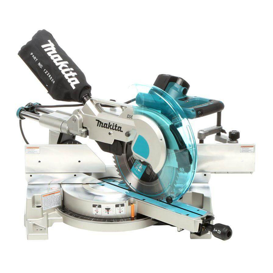
Makita LS1216 Technical Information
Slide compound saw 305mm 12"
Hide thumbs
Also See for LS1216:
- Instruction manual (172 pages) ,
- Instruction manual (168 pages) ,
- Instruction manual (160 pages)
Table of Contents
Advertisement
Quick Links
T
ECHNICAL INFORMATION
Models No.
Description
C
ONCEPT AND MAIN APPLICATIONS
LS1216 and LS1216L are upgraded sister tools of LS1214 series models,
featuring DXT (Deep eXact cutting Technology) achieved by our consistent
pursuit of cutting larger size workpiece but with higher accuracy.
The features and benefits of DXT are:
Deep cutting
3-Stage reduction gear unit and Movable rear blade guard provide larger
capacities of cutting 203mm (8
Baseboard (Skirt board) which are typical workpieces of slide compound saws.
eXact cutting
Precise and exact cutting obtained by employing:
Double sliding mechanism
Double sliding guide fence
Quick and accurate miter angle lock, etc
LS1216L additionally features laser marker for easy cut line alignment.
S
pecification
Voltage (V)
110
120
220
230
240
Specification
Continuous rating input: W
Rated amperage for North America: A
No load speed: min-
Diameter
Saw blade:
mm (")
Hole diameter
Electric brake
Soft start
Electronic
control
Constant speed
Laser marker
Lock-off switch
Protection against electric shock
Power supply cord: m (ft)
Net weight*
: kg (lbs)
1
Net weight*
: kg (lbs)
2
*1 Weight according to EPTA-Procedure 01/2003, with
*2 Weight according to EPTA-Procedure 01/2003, with
See next page for the cutting capacities.
LS1216, LS1216L
Slide Compound Saw 305mm (12")
"
) Crown molding leaning against fence and
Current (A)
Cycle (Hz)
15
15
7.9
7.6
7.2
Model No.
= rpm
1
Continuous Rating (W)
Input
50/60
1,650
50/60
---
50/60
1,650
50/60
1,650
50/60
1,650
LS1216
European countries: 30, Other countries: 25.4 (1)
No
Double insulation
Chile, Brazil, Australia: 2.0 (6.6), Other countries: 2.5 (8.2)
26.3 (58.0)
26.5 (58.4)
saw blade without "Blocking mechanism at the rest position"
TCT
saw blade with "Blocking mechanism at the rest position"
TCT
L
Dimensions: mm (")
Length (L)
Width (W)
Height (H)
Output
800
800
900
900
900
LS1216L
1,650
15
3,200
305 (12)
Yes
Yes
Yes
Yes
Yes
26.4 (58.2)
26.6 (58.6)
PRODUCT
P 1/ 35
H
W
806 (31-3/4)
640 (25-1/4)
721 (28-3/8)
Max. Output (W)
2,700
2,700
2,400
2,400
2,400
Advertisement
Table of Contents

Related Manuals for Makita LS1216


Summary of Contents for Makita LS1216
- Page 1 Slide Compound Saw 305mm (12") ONCEPT AND MAIN APPLICATIONS LS1216 and LS1216L are upgraded sister tools of LS1214 series models, featuring DXT (Deep eXact cutting Technology) achieved by our consistent pursuit of cutting larger size workpiece but with higher accuracy.
- Page 2 P 2/ 35 pecification (cont.) Cutting capacities [Height x Width in mm (")] All countries except European countries Bevel angle 45 degrees left 0 degree 45 degrees right Miter angle 61 x 382 (2-3/8 x 15) 92 x 382 (3-5/8 x 15) 44 x 382 (1-3/4 x 15) 71 x 363 (2-13/16 x 14-1/4) 107 x 363 (4-1/4 x 14-1/4)
-
Page 3: Flat Washer
Item No. Description Portion to lubricate Lubricant Amount Armature Gear teeth Makita grease SG No.0 in total Spiral bevel gear 32 a little Helical gear 14 Groove of its shaft portion for Woodruff key 4 Makita grease FA No.2 Helical gear 27... - Page 4 Portion where Center cover contacts Portion where Upper fence R complete contacts Lower fence R Portion where Guide fence contacts Portion where Upper fence L complete contacts Makita grease SG No.0 Lower fence L Portion where Guide fence contacts a little Arm complete...
- Page 5 Whole portion Stopper pin Portion where Front arm complete contacts Torsion spring 40 Spring roll ends where Dront arm complete contacts Makita grease a little Front arm complete Portion where Blade case complete contacts SG No.0 Portion where Rib on the reverse of Turn base contacts...
-
Page 6: Spring Washer
P 6/ 35 epair Note: Remove Saw blade and Safety cover section before disassembling. [3] DISASSEMBLY/ASSEMBLY Fig. 4 [3]-1. Blade case section, Motor section Strain relief with Bind CT4x12 DISASSEMBLING Tapping screw (2pcs each.) 1) Push Knob 20 to hook Stopper pin with Blade case complete kept in its upper dead point. -
Page 7: Table Of Contents
P 7/ 35 epair [3] DISASSEMBLY/ASSEMBLY [3]-1. Blade case section, Motor section (cont.) Fig. 9 M6x16 H. S. set screw (flat point) DISASSEMBLING for pressing Rod 16 (8) Loosen M6x16 H. S. set screw (flat point) slightly to remove Rod 16 in the next step. M6x20 Hex Loosen M6x20 Hex socket head bolt to make the spring force socket head bolt... -
Page 8: Blade
P 8/ 35 epair [3] DISASSEMBLY/ASSEMBLY [3]-1. Blade case section, Motor section (cont.) DISASSEMBLING 13) To remove Motor section from Blade case section, remove Carbon brushes first. 14) Regarding LS1216L only, remove Lead cover holder and 4x18 Tapping screw then disconnect Connectors for Laser circuit. -
Page 9: Torsion Spring
Lead holder cover Tapping screw (LS1216L) / Cover holder (LS1216) [3]-2. Spiral bevel gear 32, Helical gears 14, Helical gears 27, Helical gears 28 DISASSEMBLING Note: Without removing Guard, Link plate and Motor section, disassembling the subject parts is impossible. -
Page 10: Section
P 10/ 35 epair [3] DISASSEMBLY/ASSEMBLY [3]-2. Spiral bevel gear 32, Helical gears 14, Helical gears 27, Helical gears 28 (cont.) DISASSEMBLING Remove Ball bearing 608DDW from Helical gear 14 using 1R269. Remove Retaining ring S-12 from Helical gear 14 using 1R291. If it is difficult to remove the ring in this way, remove the ring while pushing Retaining ring S-12 with 1R291. -
Page 11: Complete
P 11/ 35 epair [3] DISASSEMBLY/ASSEMBLY [3]-2. Spiral bevel gear 32, Helical gear 14, Helical gear 27, Helical gear 28 (cont.) Fig. 30 DISASSEMBLING (11) Remove Ball bearing 608DDW from Spindle using 1R269. and then Ball bearing 608DDW remove Retaining ring S-15 using 1R291. (Fig. 28) (12) Receive Ball bearing 6002DDW with U-shape table of Arbor press, Retaining ring S-15 and press down Spindle as illustrated in Fig. -
Page 12: Section
8) Secure Grease holder to Bearing box complete with two Bind CT4x12 Tapping screws. Apply Makita grease FA No. 2 to the groove of Helical gear 14 and then insert Woodruff key 4 into the groove. While holding woodruff key 4 with finger, secure Spiral bevel gear 32 with Woodruff key 4 in the shaft portion of Helical gear 14. -
Page 13: Stop Ring E-
P 13/ 35 epair [3] DISASSEMBLY/ASSEMBLY [3]-3. Lock Lever Section (exclusively for the specifications with Locking mechanism of Blade case complete at the upper dead point) DISASSEMBLING 1) Remove two M4x10 Hex socket head bolts and two Flat washers 4, then remove Lock lever and Torsion spring 8. (Fig. 38) 2) Remove two CT4x16 Tapping screws and separate Rod 8 from Rod holder. -
Page 14: Blade
P 14/ 35 epair [3] DISASSEMBLY/ASSEMBLY [3]-4. Safety cover A ASSEMBLING (1) Assemble Safety cover A section. (Fig. 42) And then mount the Safety cover A section to Safety cover B. (Fig. 43) (2) Mount the Safety cover section to Blade case complete as illustrated in Fig. 44. Fig. -
Page 15: Section
P 15/ 35 epair [3] DISASSEMBLY/ASSEMBLY [3]-5. Turn Base, Base DISASSEMBLING (1) Remove Fence section, Kerf board and Miter scale plate from Turn base and Base. (Fig. 45) (2) Remove Turn base section from Base. (Fig. 46) Fig. 45 1. Remove Upper fence, Lower 2. -
Page 16: Complete
P 16/ 35 epair [3] DISASSEMBLY/ASSEMBLY [3]-6. Positive lock mechanism of Turn base Fig. 47 DISASSEMBLING (1) Remove Stop ring E-7. (Fig. 47) Stop ring E-7 Grip 50, Compression spring 11, Flat washer 10 and Cam can be removed. (2) Remove two CT4x16 Tapping screws and Plate from Turn base complete. Miter lock plate B complete and Pin 6 are removed. -
Page 17: Knob
Fig. 54. Flat washer 6 ASSEMBLING Take the disassembling step in reverse. Note: Apply Makita grease SG No.00 to O ring 7 that is fit into Stopper pin. Refer to Fig. 3. Ring 6... -
Page 18: Section
P 18/ 35 epair [3] DISASSEMBLY/ASSEMBLY [3]-9. Front arm section DISASSEMBLING Refer to Fig. 55. Fig. 55 1) Loosen M6x8 Hex. socket set screw (2pcs.) on Pipe Front arm Pipes of Front arm complete holder and remove Pipe holder. complete M6x8 Hex. -
Page 19: Section
P 19/ 35 epair [3] DISASSEMBLY/ASSEMBLY [3]-10. Arm complete, Arm holder (cont.) Fig. 61 DISASSEMBLING Position plate (7) Remove CT 4x16 Tapping screw. Arm holder cover and Position plate can be removed. (Fig. 61) Arm holder (8) Pull out Center shaft while pushing Leaf spring as drawn in Fig. 62. cover (9) After removing Leaf spring from Lock pin 8, pull out Lock pin 8 and CT 4x16... -
Page 20: Blade
[3]-11. Laser Mechanism (for LS1216L only) DISASSEMBLING Note: Makita-operated or authorized repair shops do the maintenance of Laser mechanism. (1) As shown in Fig. 18, remove 4x18 Tapping screw and Lead cover holder. Then disconnect Connectors of Laser circuit from that of Power supply cord, and remove Lead cover. -
Page 21: Blade
P 21/ 35 epair [3] DISASSEMBLY/ASSEMBLY [3]-11. Laser Mechanism (for LS1216L only: cont.) Fig. 73 the surface of ASSEMBLING Block C Take the disassembling step in reverse. Note: 1) Hook one end of Torsion springs 9(A) to the groove of Laser circuit complete, and hook the other end to the groove of Block B. -
Page 22: Blade
P 22/ 35 epair [4] ADJUSTMENT [4]-3. Guide fence 1) Pretighten M8x25 Hex socket head bolt (with flat washer and spring washer) at the threaded hole designated with gray arrow. The round shape around the thread hole is smaller than the others (designated with black arrow) for M8x25 Hex socket head bolts. -
Page 23: Blade
P 23/ 35 epair [4] ADJUSTMENT [4]-5. Laser (for LS1216L only) (1) Remove M10x20 Hex flange head bolt, Outer flange, Inner flange and Blade. Then separate Safety cover section from Blade case complete. (Fig. 84) (2) Remove Protector. (Fig. 85) (3) Place Flat washer 16 on Spindle (Fig. - Page 24 P 24/ 35 epair [4] ADJUSTMENT [4]-5. Laser (for LS1216L only: Cont.) Note: 1) In the process (10) and (11), backlash of M4x6 Hex socket set screw A or B may be happened. Therefore, turn each M4x6 Hex socket set screw clockwise carefully to prevent backlash. 2) Be sure to distinguish the role of M4x6 Hex socket set screw A and M4x6 Hex socket set screw B.
-
Page 25: Blade
P 25/ 35 ircuit diagram Fig. D-1 220-240V area where Radio interference suppression is required Color index of lead wires' sheath Black Orange White Blue Purple Yellow Brush holder Brush holder Handle Dust nozzle Motor housing Choke coil Brush holder of Brush holder of Handle side Dust nozzle side... -
Page 26: Blade
P 26/ 35 ircuit diagram Fig. D-2 UK 110V only Color index of lead wires' sheath Orange Black White Blue Yellow Brown Brush holder Brush holder Handle Dust nozzle Motor housing Brush holder of Brush holder of Handle side Dust nozzle side Field (viewed from Armature gear side) -
Page 27: Blade
P 27/ 35 ircuit diagram Fig. D-3 Argentina Color index of lead wires' sheath Black Orange White Blue Purple Yellow Brown Brush holder Brush holder Handle Dust nozzle Motor housing Brush holder of Brush holder of Handle side Dust nozzle side Switch for protection Field of brake coil... -
Page 28: Blade
P 28/ 35 ircuit diagram Fig. D-4 220- 240V area where Radio Interference Suppression is not required Color index of lead wires' sheath Black Orange White Blue Purple Yellow Brush holder Brush holder Handle Dust nozzle Motor housing Brush holder of Brush holder of Handle side Dust nozzle side... -
Page 29: Blade
P 29/ 35 ircuit diagram Fig. D-5 110-127V area except UK Color index of lead wires' sheath Black Orange Blue White Yellow Brush holder Brush holder Handle Dust nozzle Motor housing Brush holder of Brush holder of Dust nozzle side Handle side Blue is used for Field... - Page 30 P 30/ 35 iring diagram Wiring around Case of LS1216L Fig. D-6 Inside of Case Outside of Case Fix Lead wires (red) with lead wire holder. Case Assemble Power supply Case circuit (Transformer and Circuit plate) to Case. Transformer Controller Fix the Lead wires (black and white) with Lead wire side...
- Page 31 P 31/ 35 iring diagram Fig. D-8 Wiring in Motor housing and Handle for Argentina and 220 - 240V area where Radio interference suppression is required. Terminal Field lead wires have to be tightened Do not put Lead wires on block in the Motor housing so as not to these ribs.
- Page 32 P 32/ 35 iring diagram Fig. D-9 Wiring in Motor Housing and Handle for area 220 - 240V where Radio Interference suppression is not required. Insulated terminal Do not put Lead wires on Field lead wires have to be tightened these ribs.
- Page 33 P 33/ 35 iring diagram Fig. D-10 Wiring in Motor Housing and Handle for 110 - 127V area other than UK Insulated terminal Field lead wires have to be tightened in Motor housing so as not to touch Do not put Lead wires on these ribs. Armature.
- Page 34 P 34/ 35 iring diagram Fig. D-11 Wiring in Motor housing and Handle for UK 110V Terminal Field lead wires have to be tightened block in the Motor housing so as not to Do not put Lead wires on ribs. touch Armature.
-
Page 35: Blade
P 35/ 35 iring diagram Fig. D-12 Wiring of Laser circuit complete of LS1216L for all countries Pay attention not to pinch Lead wires between ribs of Blade case designated in gray color and Lead cover. Route the Lead wires of Boss Laser circuit complete between Rib C and Boss.
Need help?
Do you have a question about the LS1216 and is the answer not in the manual?
Questions and answers