
Related Manuals for Sony HDRC-4000


Summary of Contents for Sony HDRC-4000
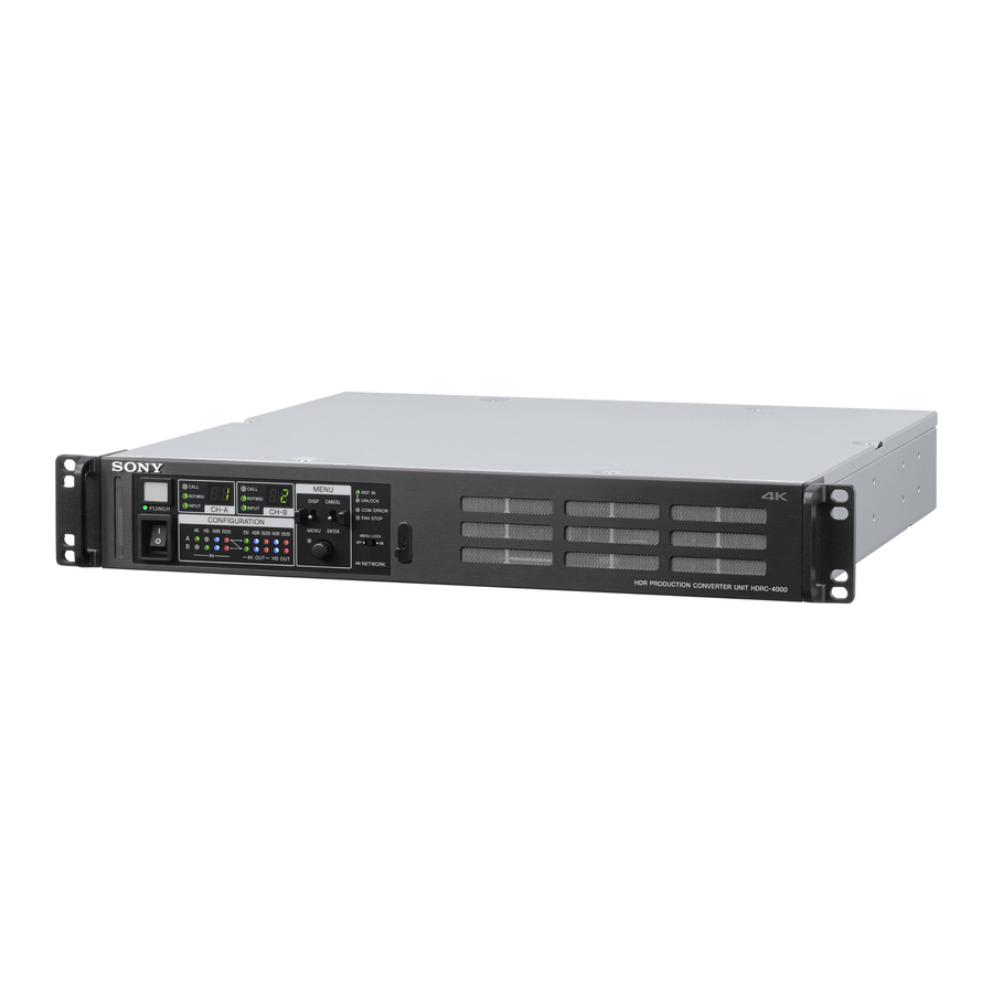
- Page 1 HDR PRODUCTION CONVERTER UNIT HDRC-4000 OPERATION MANUAL [English] 1st Edition (Revised 2)
-
Page 2: Table Of Contents
Table of Contents Overview..............3 Features ................3 System Configuration ............5 Name and Function of Parts ........6 Front Panel ..............6 Rear Panel ..............7 Connection and Setup..........8 System Connection ............8 Relationship between Connection Type and BNC Connector Assignment ..........12 Supported Formats and Input/Output Interface .....13 Status Display ............ -
Page 3: Overview
The 4K output and HD output signal conversion settings can be configured independently. The HDRC-4000 HDR Production Converter Unit converts HDR video signals using the OETF standard. OETF supports Dual system signal processing several standards, including Sony’s original S-Log3 curve, Equipped with a dual system (channel A, channel B) signal SMPTE ST 2084 (PQ) and ITU-R BT. - Page 4 The audio signal with a delay matching the video signal is embedded in the output signal. Remote control Supports the remote control by Sony system camera products. Format setting, HDR/SDR setting, OETF setting, color space setting, image quality setting, file operation, and menu operation are supported from an RCP-1500 series Remote Control Panel or an MSU-1000 series Master Setup Unit.
-
Page 5: System Configuration
System Configuration HDRC-4000 HDR Production Converter Unit 4K-SDR 4K-HDR (S-Log3) Channel A HD-SDR HDRC-4000 Channel B HDR Production 4K-HDR 4K-HDR Converter Unit (HLG) (S-Log3) Channel A SDI Router HD-SDR Switcher BPU4000/4500 Channel B Baseband Processor Unit 4K-SDR HD-SDR 4K-SDR HDC4300 Color Camera... -
Page 6: Name And Function Of Parts
Name and Function of Parts Front Panel c MENU control block DISP/MENU lever and indicator CANCEL/ENTER lever MENU CALL REF IN CALL MENU UNLOCK RCP/MSU RCP/MSU DISP CANCEL COM ERROR INPUT INPUT DISP CANCEL CH A CH B POWER FAN STOP CONFIGURATION MENU ENTER... -
Page 7: Rear Panel
4K OUT setting Flashing: Indicates that an external control device (MSU- 2SI: Lights up when the 4K output format is 2SI. 1000 Master Setup Unit or RCP-1500 series Remote HDR: Lights up when the 4K output or HD×4 output OETF Control Panel) is not connected successfully when the setting is HDR. -
Page 8: Connection And Setup
Link-1 Link-2 Link-3 Link-4 REFERENCE HD INPUT 4K INPUT External control device 4K INPUT HDRC-4000 Link-1 Link-2 Link-3 Link-4 Channel B 4K input 14K Single-Link, 4K Dual- Link, or 4K Quad-Link input Channel A HD monitor output Channel A 4K output 23G/HD-SDI×4 inputs... - Page 9 Settings Setting Menu/Page Item Set value System format settings CONFIGURATION/ SYSTEM RESOLUTION 3840×2160 (fixed) <SYSTEM> FORMAT FREQUENCY Set 1.000 or 1.001 (C01) FRAME RATE Set the video frame frequency Channel A operation CONFIGURATION/ AIR MATCHING Channel A AIR MATCHING function on/ mode settings <CHANNEL A SETTINGS>...
- Page 10 Setting Menu/Page Item Set value Channel B input/output CONFIGURATION/ INPUT (4K / HD / HDx4IN / CH.A) Selects channel B input signal video format settings <CHANNEL B SETTINGS> (HD-SDI / 3G(Lv-B) / Displays the input signal auto sensing (C04) 3G(Lv-A) / 6G-SDI / result 12G-SDI) (AUTO / 2SI / SQD)
- Page 11 (disabled) (3G/HD-SDI × 4ch) Link-1 Link-2 Link-3 Link-4 REFERENCE HD INPUT 4K INPUT 4K INPUT HDRC-4000 Link-1 Link-2 Link-3 Link-4 Channel B 4K input (3G/HD-SDI × 4ch) Channel A HD monitor output (HD-SDI) Channel A 4K output (3G/HD-SDI × 4ch)
-
Page 12: Relationship Between Connection Type And Bnc Connector Assignment
Relationship between Connection Type and BNC Connector Assignment The names of the input/output interfaces in Table 1 correspond then check the signal assignments to BNC connectors in to BNC connector assignments in Tables 2 and 3. Check the Tables 2 and 3. input/output interface for the format you want to use in Table 1, Table 1: Relationship between 4K operation mode/signal format and input/output interface System format... -
Page 13: Supported Formats And Input/Output Interface
Supported Formats and Input/Output Interface 4K input/output connectors 4K input/output formats System format 4K input/output Frequency Frame rate Input/output format Input/output interface 1.001 59.94 2160/59.94P 12G-SDI No division 3G-SDI Level-A/B 29.97 2160/29.97P 6G-SDI No division 3G-SDI Level-B 2160/29.97PsF 3G-SDI Level-B HD-SDI 23.98 2160/23.98P... - Page 14 HD input/output connectors HD input formats System format HD input Frequency Frame rate Input format Input interface 1.001 59.94 1080/59.94P 3G-SDI Level-A/B 1080/59.94i HD-SDI 1080/29.97PsF HD-SDI 720/59.94P HD-SDI 29.97 1080/29.97PsF HD-SDI 23.98 1080/23.98PsF HD-SDI 1.000 1080/50P 3G-SDI Level-A/B 1080/50i HD-SDI 1080/25PsF HD-SDI 720/50P...
-
Page 15: Status Display
Status Display Menu Settings The unit and system status can be monitored using text The unit and system status can be monitored and various characters superimposed on the HD monitor output signal. settings can be checked and modified using the menu displayed in the HD monitor output. - Page 16 To set a menu item Menu Description If ? (question mark) is displayed to the left of the page number, CONFIGURATION Use to set basic settings of the unit (excludes push the control knob to change to the , cursor. Settings on image quality settings).
-
Page 17: Menu Tree
To cancel all settings Menu Tree Move the , cursor to ESC and push the control knob. The * (asterisk) changes back to ,, and all the changes for the item are discarded. CONFIGURATION menu To exit the menu SYSTEM SYSTEM FORMAT In menu display mode, set the DISP/MENU lever to MENU. - Page 18 GAMMA CHANNEL A OTHERS BARS (S25) GAMMA (C10) CH.A CH.B TABLE TYPE STEP HD DOWNCONV FILTER LEVEL CHANNEL B CHARACTER LEVEL GAMMA CH.B HD MONI TABLE STEP SETUP menu LEVEL WHITE CLIP CHANNEL A HDRt HDR (S26) WHITE CLIP BLACK CHANNEL A LEVEL (S11)
- Page 19 FILE menu GAMMA CHANNEL A (S43) GAMMA TABLE SCENE FILE CHANNEL A CHANNEL B (F01) SCENE FILE No. GAMMA RECALL TABLE STORE STANDARD 4KtHD RECALL HD DETAIL DETAIL CHANNEL B (S51) HD DETAIL SCENE FILE No. LEVEL RECALL LIMITER STORE CRISP STANDARD RECALL...
- Page 20 DIAGNOSIS menu BOARD STATUS (D01) DCP1 DCP2 ROM VERSION (D02) UPDATER DCP1 DCP2 4K-POST 2K-POST SERIAL NO. MODEL (D03) IP ADDRESS IP ADDRESS (CH.A) (D04) IP ADDRESS (CH.B) SUBNET MASK DEFAULT GATEWAY MAC ADDRESS LAN STATUS AUTO NEGOTIATION (D05) CONNECTION SPEED DUPLEX MODE LINK CONDITION CNS STATUS...
-
Page 21: Menu List
Menu List Legend The following conventions are used in the menu tables. Settings ON, OFF, 0, etc.: Factory default settings shown underlined. ENTER to execute: Execute by pushing the control knob or setting the CANCEL/ENTER lever to the ENTER position. CONFIGURATION menu Use to set basic settings of the unit (excludes image quality settings). - Page 22 Page name Item Set value Meaning Page No. <CHANNEL A AIR MATCHING OFF, ON AIR MATCHING function on/off setting. SETTINGS> Conversion so that roughly the same “look” is obtained on a monitor displaying the input HDR signal and a monitor displaying the output HDR signal.
- Page 23 Page name Item Set value Meaning Page No. <CHANNEL B AIR MATCHING OFF, ON AIR MATCHING function on/off setting. SETTINGS> Conversion so that roughly the same “look” is obtained on a monitor displaying the input HDR signal and a monitor displaying the output HDR signal.
- Page 24 Page name Item Set value Meaning Page No. <OUTPUT DELAY1> CHANNEL A DELAY MODE NORMAL, MINIMUM Delay mode setting NORMAL: Normal delay mode (delay of one or more frames) MINIMUM: Minimum delay mode FRAME SYNC OFF, ON Frame synchronizer on/off setting OUTPUT 4K 1 to 5/(frame rate)s, 1LINE, 2LINE, Output signal delay relative to reference sync...
- Page 25 Page name Item Set value Meaning Page No. <HD DEINTERLACE> CHANNEL A MODE MOTION DETECTION, Deinterlacing mode setting (converting from FIELD COMBINATION(Weave), interlaced to progressive). (Enabled when the FIELD EXTENSION(Bob), system format frame rate is 59.94 or 50) PsF CONVERSION MOTION DETECTION: Detect motion, and apply FIELD EXTENSION(Bob) for areas with motion and FIELD COMBINATION(Weave) for...
- Page 26 Page name Item Set value Meaning Page No. <OTHERS> BARS CH.A OFF, ON Color bar output on/off setting CH.B OFF, ON TYPE BAR 16:9(100%), BAR 16:9(75%), Color bar type SDI CHECK FIELD, Y-RAMP, Y/C- RAMP HD DOWNCONV FILTER 1 to 4, 1(V:0.3), 1(V:0.6) 4K video signal to HD signal down-converter filter type CHARACTER LEVEL...
- Page 27 SETTING MODE SONY SYSTEM CAMERA, Select whether the source of the input video OTHERS signal is a Sony made system camera or not MASTER BLACK –99.9 to 99.9, 0.0 Set the master black value of the input video signal source...
- Page 28 SETTING MODE SONY SYSTEM CAMERA, Select whether the source of the input video OTHERS signal is a Sony made system camera or not MASTER BLACK –99.9 to 99.9, 0.0 Set the master black value of the input video signal source...
- Page 29 Page name Page No. Item Set value Meaning <HDRtSDR GAIN> CHANNEL A HDRtSDR GAIN 0.0dB to –15.0dB HDR-to-SDR conversion gain Displays the SDR percentage corresponding to CONTRAST HDR 100% after conversion using HDRtSDR GAIN (display only) CHANNEL B HDRtSDR GAIN 0.0dB to –15.0dB HDR-to-SDR conversion gain Displays the SDR percentage corresponding to...
- Page 30 Page name Page No. Item Set value Meaning <KNEE> CHANNEL A KNEE OFF, ON HDR-to-SDR conversion knee (high luminance compression for HDR) function on/off setting POINT: R: –99 to 99, 0 Knee point setting of knee function G: –99 to 99, 0 B: –99 to 99, 0 M: –99 to 99, 0 SLOPE:...
- Page 31 Page name Page No. Item Set value Meaning <GAMMA> CHANNEL A GAMMA OFF, ON HDR-to-SDR conversion gamma on/off setting TABLE STANDARD, HYPER Type of gamma curve 1 to 7, 5 (STANDARD) 1 to 4 (HYPER) STEP 0.90, 0.85, 0.80, 0.75, 0.70, 0.65, Gamma strength (step) 0.60, 0.55, 0.50, 0.45, 0.40, 0.35 LEVEL...
- Page 32 SETTING MODE SONY SYSTEM CAMERA, Select whether the source of the input video OTHERS signal is a Sony made system camera or not MASTER BLACK –99.9 to 99.9, 0.0 Set the master black value of the input video signal source Fixed to absolute value of 0.0 when DISPLAY...
- Page 33 SETTING MODE SONY SYSTEM CAMERA, Select whether the source of the input video OTHERS signal is a Sony made system camera or not MASTER BLACK –99.9 to 99.9, 0.0 Set the master black value of the input video signal source Fixed to absolute value of 0.0 when DISPLAY...
- Page 34 Page name Page No. Item Set value Meaning <DE-GAMMA> CHANNEL A DE-GAMMA STANDARD, HYPER Type of inverse gamma curve (Disabled when DISPLAY REFERRED on the <SYSTEM> page is ON) 1 to 7, 5 (When set to STANDARD. Disabled when DISPLAY REFERRED on the <SYSTEM> page is ON) 1 to 4 (When set to HYPER.
- Page 35 SETTING MODE SONY SYSTEM CAMERA, Select whether the source of the input video OTHERS signal is a Sony made system camera or not MASTER BLACK –99.9 to 99.9, 0.0 Set the master black value of the input video signal source...
- Page 36 Page name Page No. Item Set value Meaning <GAMMA> CHANNEL A GAMMA OFF, ON SDR-to-SDR conversion gamma on/off setting TABLE STANDARD, HYPER Type of gamma curve (same value as DE- GAMMA, display only) 1 to 7 (STANDARD. Display only) 1 to 4 (HYPER.
- Page 37 HDt4K Configure settings for up-converting from HD to 4K. Page name Page No. Item Set value Meaning <HD DETAIL CHANNEL A REDUCTION> HD DETAIL OFF, ON Detail (contour emphasis) reduction function REDUCTION on/off setting LEVEL –99.9 to 99.9, 0 Detail reduction function level FREQUENCY –99.9 to 99.9, 0 Frequency response for detail component...
- Page 38 Page name Page No. Item Set value Meaning <WHITE BALANCE> CHANNEL A WHITE BALANCE OFF, ON White balance adjustment function on/off setting ((OFF) when ADDITIONAL PAINT is OFF) –99.9 to 99.9, 0 White balance adjustment (R gain) –99.9 to 99.9, 0 White balance adjustment (B gain) CHANNEL B WHITE BALANCE OFF, ON...
- Page 39 Page name Page No. Item Set value Meaning <DETAIL> DETAIL CH. A: OFF, ON Detail function on/off setting ((OFF) when input is HD×4) CH. B: OFF, ON 4K DETAIL CH. A: OFF, ON 4K output signal detail function on/off setting ((OFF) when the input is 4K and ADDITIONAL CH.
- Page 40 FILE menu Use to set file-related settings (saving, loading, clearing) of the unit. Page name Page No. Item Set value Meaning <SCENE FILE> CHANNEL A SCENE FILE No. 1 to 5 Specify the scene file number RECALL Recall the specified scene file STORE Store settings in the specified scene file STANDARD...
- Page 41 NETWORK menu Use to configure network-related settings. Page name Item Set value Meaning Page No. <IP ADDRESS IP ADDRESS(CH.A) 0.0.0.0 to 255.255.255.255 IP address setting of unit (Set different IP SETTINGS> addresses for channel A and channel B) IP ADDRESS(CH.B) 0.0.0.0 to 255.255.255.255 SUBNET MASK 0.0.0.0 to 255.255.255.255...
- Page 42 Page name Item Set value Meaning Page No. <ROM VERSION> Version and date of main software Software version information Model name Comment OS version, date UPDATER Version and date of update software V x.xx ROM version of SY PLD V x.xx ROM version of SDI PLD V x.xx ROM version of DEC PLD...
- Page 43 Page name Item Set value Meaning Page No. <12G/6G-SDI STATUS> SDI IN Displays the 12G/6G-SDI input status NO SIGNAL: Input signal is not detected CH.A 4K OK: Detected successfully CH.B 4K ERROR: Signal detected, but an error exists (3G/HD-SDI): Status is not displayed when input is 3G/HD-SDI SDI OUT Displays the 12G/6G-SDI output status...
-
Page 44: File System
File System The unit features a file system for managing data. Operation from MSU Change the scene file item to the desired value. File Configuration Press the STORE button in the function control block The file system supports the following three types of files. on the operation panel. -
Page 45: Reference Files
All-settings file operations Select [Converter All-Settings] t [Store/Recall] in the menu. Operation procedures Select the number of the all-settings file you want to Unit recall. Store Clearing an all-settings file All current settings All-settings file (excluding network Operation using ALL-SETTINGS FILE page of FILE settings) menu Recall... -
Page 46: Initialization
Select [Reference] t [Reference Store] in the menu. Reference files are stored in the unit, and the display of numeric data is indicated as “0” (excluding some items). Recalling a reference file Operation using SCENE FILE page of FILE menu Select STANDARD t RECALL of the channel you want to recall on the SCENE FILE page. -
Page 47: Appendix
FRAME RATE UNMATCH Input signal and menu setting frame rate mismatch. SONY WILL NOT BE LIABLE FOR DAMAGES OF ANY KIND RESULTING FROM A FAILURE TO IMPLEMENT PROPER SECURITY MEASURES ON TRANSMISSION DEVICES, UNAVOIDABLE DATA LEAKS RESULTING FROM TRANSMISSION SPECIFICATIONS, OR SECURITY PROBLEMS OF ANY KIND. -
Page 48: Specifications
OTHER REASON WHATSOEVER. 3G-SDI: SMPTE ST424/425 Level-A/B, OUT-B MAIN (3G/ • SONY WILL NOT BE LIABLE FOR CLAIMS OF ANY KIND 0.8 Vp-p, 75 ohms, 2.970 Gbps/2.967 Gbps HD-SDI OUTPUT) MADE BY USERS OF THIS UNIT OR MADE BY THIRD HD-SDI: SMPTE ST292, 0.8 Vp-p, 75 ohms,... - Page 49 Sony Corporation HDRC-4000 (SY) 4-694-920-13 (1) © 2017...
Need help?
Do you have a question about the HDRC-4000 and is the answer not in the manual?
Questions and answers