Table of Contents
Advertisement
Quick Links
Advertisement
Table of Contents

Related Manuals for Sony HDRC-4000


Summary of Contents for Sony HDRC-4000
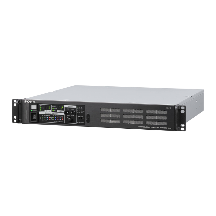
- Page 1 HDR PRODUCTION CONVERTER UNIT HDRC-4000 OPERATION MANUAL [English] 1st Edition...
-
Page 2: Table Of Contents
Table of Contents Overview..............3 Features ................3 System Configuration ............4 Name and Function of Parts ........5 Front Panel ..............5 Rear Panel ..............6 Connection and Setup..........7 System Connection ............7 Relationship between Connection Type and BNC Connector Assignment ..........12 Status Display ............13 Displaying the Status Screen ........13 Status Display Screen ...........13 Menu Settings ............ -
Page 3: Overview
• HD × single system: 3G/HD-SDI • HD monitor × single system: HD-SDI External reference signal The HDRC-4000 HDR Production Converter Unit converts HDR video signals using the OETF standard. OETF supports The output signal can be synchronized to an external several standards, including Sony’s original S-Log3 curve,... -
Page 4: System Configuration
System Configuration HDRC-4000 HDR Production Converter Unit 4K-SDR 4K-SDR (S-Log3) Channel A HD-SDR HDRC-4000 Channel B HDR Production 4K-HDR 4K-SDR Converter Unit (HLG) (S-Log3) Channel A SDI Router HD-SDR Switcher Channel B BPU4000/4500 4K-SDR Baseband Processor Unit HD-SDR 4K-SDR HDC4300 Color Camera... -
Page 5: Name And Function Of Parts
Name and Function of Parts Front Panel c MENU control block DISP/MENU lever and indicator CANCEL/ENTER lever MENU CALL CALL REF IN MENU UNLOCK RCP/MSU CANCEL RCP/MSU DISP COM ERROR INPUT INPUT CANCEL DISP CH A CH B POWER FAN STOP CONFIGURATION MENU ENTER... -
Page 6: Rear Panel
HD OUT setting CNS MODE setting in <CNS SETTING> is set to BRIDGE HDR: Lights up when the HD output OETF setting is HDR. or MCS. 2020: Lights up when the HD output color space setting is Off: Indicates that the LAN cable is not connected or network BT.2020. -
Page 7: Connection And Setup
(4K Quad-Link) Link-1 Link-2 Link-3 Link-4 REFERENCE HD INPUT 4K INPUT External control device 4K INPUT HDRC-4000 Link-1 Link-2 Link-3 Link-4 Channel B 4K input (4K Quad-Link) Channel A HD monitor output (HD-SDI) Channel A 4K output (4K Quad-Link) Channel A HD main output... - Page 8 Settings Device Setting Menu/Page Item Set value HDRC-4000 System format settings CONFIGURATION/ SYSTEM RESOLUTION 3840×2160 (fixed) <SYSTEM> FORMAT FRAME RATE Frame frequency (C01) Channel A operation CONFIGURATION/ AIR MATCHING Channel A AIR mode settings <CHANNEL A SETTINGS> MATCHING function on/...
- Page 9 Device Setting Menu/Page Item Set value Conversion parameter SETUP/<HDR/SDR SETUP> CHANNEL A settings (S01) HDRtSDR GAIN Gain difference between (SDRtHDR GAIN) HDR signal and SDR signal of channel A MASTER BLACK Input signal master black level HDR BLACK OFFSET HDR signal master black offset relative to the SDR signal CHANNEL B...
- Page 10 Also performs HDR/SDR output signal switching. c) You can select the channel A input signal. d) When a signal from a Sony system camera is input, set the same setting that is configured on the camera. e) Adjustment using this page is not required if settings on the <HDR/ SDR SETUP>...
- Page 11 (disabled) (3G/HD-SDI × 4ch) Link-1 Link-2 Link-3 Link-4 REFERENCE HD INPUT 4K INPUT 4K INPUT HDRC-4000 Link-1 Link-2 Link-3 Link-4 Channel B 4K input (3G/HD-SDI × 4ch) Channel A HD monitor output (menu/status output only enabled) Channel A 4K output (3G/HD-SDI ×...
-
Page 12: Relationship Between Connection Type And Bnc Connector Assignment
Relationship between Connection Type and BNC Connector Assignment The names of the input/output interfaces in Table 1 correspond then check the signal assignments to BNC connectors in to BNC connector assignments in Tables 2 and 3. Check the Tables 2 and 3. input/output interface for the format you want to use in Table 1, Table 1: Relationship between operation mode/signal format and output interface Operation mode... -
Page 13: Status Display
Status Display Menu Settings The unit and system status can be monitored using text The unit and system status can be monitored and various characters superimposed on the HD monitor output signal. settings can be checked and modified using the menu displayed in the HD monitor output. - Page 14 The , cursor changes to a flashing ? (question mark). To change page Turn the control knob to change the setting. Check that the , cursor is pointing to the page number then push the control knob. To cancel a changed setting in an input field The , cursor changes to a flashing ? (question mark).
-
Page 15: Menu Tree
SETUP menu Menu Tree HDR/SDR SETUP CHANNEL A CONFIGURATION menu (S01) HDRtSDR GAIN SDRtHDR GAIN HDR CONTRAST SYSTEM SYSTEM FORMAT MASTER BLACK (C01) RESOLUTION HDR BLACK OFFSET FREQUENCY CHANNEL B FRAME RATE HDRtSDR GAIN ADVANCED PAINT MODE SDRtHDR GAIN CH.A HDR CONTRAST CH.B MASTER BLACK... - Page 16 PAINT menu FILE menu INPUT:DETAIL ADVANCED PAINT MODE REFERENCE STORE FILE REDUCTION (P01) CH.A (F01) STANDARD CH.B CONFIGURATION FILE STORE CHANNEL A (F02) LOAD (RECALL) HD DETAIL REDUCTION CLEAR LEVEL CHANNEL B FILE CLEAR ALL SETTINGS HD DETAIL REDUCTION LEVEL (F03) ALL CONFIGURATION FILES INPUT:WHITE&GAIN...
-
Page 17: Menu List
Menu List Legend The following conventions are used in the menu tables. Settings ON, OFF, 0, etc.: Factory default settings shown underlined. ENTER to execute: Execute by pushing the control knob or setting the CANCEL/ENTER lever to the ENTER position. CONFIGURATION menu Page name Item... - Page 18 Page name Item Set value Meaning Page No. <CHANNEL A AIR MATCHING OFF, ON AIR MATCHING function on/off setting. SETTINGS> Conversion so that roughly the same “look” is obtained on a monitor displaying the input HDR signal and a monitor displaying the output HDR signal.
- Page 19 Page name Item Set value Meaning Page No. <CHANNEL B AIR MATCHING OFF, ON AIR MATCHING function on/off setting. SETTINGS> Conversion so that roughly the same “look” is obtained on a monitor displaying the input HDR signal and a monitor displaying the output HDR signal.
- Page 20 Page name Item Set value Meaning Page No. <OUTPUT DELAY1> CHANNEL A DELAY MODE NORMAL, MINIMUM Delay mode setting NORMAL: Normal delay mode (delay of one or more frames) MINIMUM: Minimum delay mode FRAME SYNC OFF, ON Frame synchronizer on/off setting OUTPUT 4K 1 to 5LINE, 1 to 3FRAME Output signal delay relative to reference sync...
-
Page 21: Setup Menu
Page name Item Set value Meaning Page No. <CNS SETTINGS> CNS MODE LEGACY, BRIGDE, MCS Communications mode settings MCS MODE (CLIENT) (Display only) REMOTE CONTROL NO Number setting of device used for remote control (remote control is disabled when set to CH.A 0 to 96 MASTER IP ADDRESS... - Page 22 Page name Item Set value Meaning Page No. <BLACK CHANNEL A ADJUSTMENT> INPUT BLACK –99 to 99, 4 Input signal black level LEVEL If BLACK setting is SDRtHDR –99 to 99, 0 HDR signal black level offset relative to SDR configured on the S01 BLACK OFFSET signal (when input is SDR)
- Page 23 Page name Item Set value Meaning Page No. <OUTPUT:DETAIL> CHANNEL A DETAIL OFF, ON Detail (contour emphasis) function on/off a) Crispening: This setting function prevents the OUTPUT 4K LEVEL: –99 to 99, 0 4K output detail level adjustment (when input is enhancement of noise adding extra detail to small picture edge...
- Page 24 Page name Item Set value Meaning Page No. <OUTPUT:SDR KNEE> CHANNEL A SDR KNEE OFF, ON Knee (high luminance compression) function on/off setting for when converting from HDR to SDR ((OFF) when input is SDR) POINT: R: –99 to 99, 0 Knee point setting of knee function G: –99 to 99, 0 B: –99 to 99, 0...
- Page 25 Page name Item Set value Meaning Page No. <INPUT&OUTPUT:SDR CHANNEL A GAMMA> INPUT&OUTPUT SDR GAMMA TABLE STANDARD, HYPER Type of gamma curve when the input or output is SDR 1 to 7, 5 (STANDARD) 1 to 4 (HYPER) OUTPUT SDR OFF, ON Gamma function on/off setting for SDR output GAMMA...
- Page 26 Page name Item Set value Meaning Page No. <INPUT:WHITE&GAIN> ADVANCED PAINT MODE Advanced paint mode on/off setting CH.A OFF, ON CH.B OFF, ON CHANNEL A WHITE&GAIN ENABLE, DISABLE White balance adjustment and gain function ADJUSTMENT enable/disable WHITE R: –99 to 99, 0 White balance adjustment (R gain) B: –99 to 99, 0 White balance adjustment (B gain)
- Page 27 Page name Item Set value Meaning Page No. <OUTPUT:DETAIL> ADVANCED PAINT MODE Advanced paint mode on/off setting CH.A OFF, ON a) Crispening: This CH.B OFF, ON function prevents the enhancement of noise CHANNEL A adding extra detail to DETAIL OFF, ON Detail (contour emphasis) function on/off small picture edge setting...
- Page 28 Page name Item Set value Meaning Page No. <OUTPUT:SDR KNEE> CHANNEL A SDR KNEE OFF, ON Knee (high luminance compression) function on/off setting for when converting from HDR to SDR ((OFF) when input is SDR) POINT R: –99 to 99, 0 Knee point setting of knee function G: –99 to 99, 0 B: –99 to 99, 0...
- Page 29 Page name Item Set value Meaning Page No. <INPUT&OUTPUT:SDR CHANNEL A GAMMA> INPUT & OUTPUT SDR GAMMA TABLE STANDARD, HYPER Type of gamma curve when the input or output is SDR 1 to 7, 5 (STANDARD) 1 to 4 (HYPER) OUTPUT SDR OFF, ON Gamma function on/off setting for SDR output...
- Page 30 Item Set value Meaning Page No. <CONFIGURATION STORE Save all HDRC-4000 settings to the internal file FILE> (configuration file) specified by the “No.” item. LOAD (RECALL) Load and apply all HDRC-4000 settings from the internal file (configuration file) specified by the “No.”...
-
Page 31: Appendix
SDI INPUT error. Do not push the mesh portion of the front panel with your fingers or sharp objects. SONY WILL NOT BE LIABLE FOR DAMAGES OF ANY KIND RESULTING FROM A FAILURE TO IMPLEMENT PROPER SECURITY MEASURES ON TRANSMISSION DEVICES,... -
Page 32: Specifications
EXPIRATION OF THE WARRANTY, OR FOR ANY 1.485 Gbps/1.4835 Gbps OTHER REASON WHATSOEVER. 3G-SDI/HD-SDI selectable • SONY WILL NOT BE LIABLE FOR CLAIMS OF ANY KIND HD OUT-A MONITOR, BNC type (1+1) MADE BY USERS OF THIS UNIT OR MADE BY THIRD HD OUT-B MONITOR HD-SDI: SMPTE ST292, 0.8 Vp-p, 75 ohms,... - Page 33 Sony Corporation HDRC-4000 (SY) 4-694-920-11 (2) © 2017...
Need help?
Do you have a question about the HDRC-4000 and is the answer not in the manual?
Questions and answers