
Subscribe to Our Youtube Channel
Related Manuals for vacuubrand MZ 2 VARIO-SP


Summary of Contents for vacuubrand MZ 2 VARIO-SP
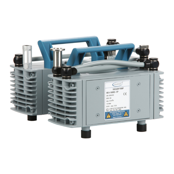
- Page 1 1 of 50 Technology for Vacuum Systems Instructions for use MZ 2 VARIO-SP MD 4 VARIO-SP Diaphragm pumps...
- Page 2 VACUU•LAN (US-Reg.No 3,704,401), VACUU•BUS , VACUU•CONTROL ® ® ® Peltronic , VARIO (US-Reg.No 3,833,788), VACUUBRAND (US-Reg.No ® ® ® 3,733,388) and also the shown company logos are registered trademarks of VACUUBRAND GMBH + CO KG in Germany and/or other countries.
- Page 3 page 3 of 50 Achtung: Die vorliegende Betriebsanleitung ist nicht in allen EU-Sprachen verfügbar. Der Anwender darf die beschriebenen Geräte nur dann in Betrieb nehmen, wenn er die vorliegende Anleitung versteht oder eine fachlich korrekte Übersetzung der voll- ständigen Anleitung vorliegen hat. Die Betriebsanleitung muss vor Inbetriebnahme der Geräte vollständig gelesen und verstanden werden, und alle geforderten Maß- nahmen müssen eingehalten werden.
- Page 4 page 4 of 50 Bemærk: Denne manual foreligger ikke på alle EU sprog. Brugeren må ikke be- tjene apparatet hvis manualen ikke er forstået. I det tilfælde skal en teknisk korrekt oversættelse af hele manual stilles til rådighed. Manual skal være gennemlæst og forstået før apparatet betjenes og alle nødvendige forholdsregler skal tages.
- Page 5 page 5 of 50 Figyelem! Ez a kezelési utasítás nem áll rendelkezésre az EU összes nyelvén. Ha a felhasználó nem érti jelen használati utasítás szövegét, nem üzemeltetheti a készüléket. Ez esetben a teljes gépkönyv fordításáról gondoskodni kell. Üzembe helyezés előtt a kezelőnek végig kell olvasnia, meg kell értenie azt, továbbá az üzemeltetéshez szükséges összes mérést el kell végeznie.
- Page 6 page 6 of 50 Attentie: Deze gebruiksaanwijzing is niet in alle talen van de EU verkrijgbaar. De gebruiker moet niet met dit apparaat gaan werken als voor hem/haar de gebruiks- aanwijzing niet voldoende duidelijk is. Bij gebruik van deze apparatuur is het nood- zakelijk een technisch correcte vertaling van de complete gebruiksaanwijzing te hebben.
- Page 7 page 7 of 50 Varning: Denna instruktion är inte tillgänglig på alla språk inom EU. Användaren får inte starta utrustningen om hon/han inte förstår denna instruktion. Om så är fallet måste en tekniskt korrekt instruktion göras tillgänglig. Instruktionen måste läsas och förstås helt före utrustningen tas i drift och nödvändiga åtgärder göres.
-
Page 8: Table Of Contents
page 8 of 50 Contents Safety information! ............. 9 Important information! ................. 9 General information ................11 Intended use..................11 Setting up and installing the equipment ..........12 Ambient conditions ................14 Operating conditions ................. 14 Safety during operation ..............16 Maintenance and repair..............18 Important information: Equipment marking (ATEX) .... -
Page 9: Safety Information
Make operating personnel aware of dangers arising from the pump and the pumped substances. VACUUBRAND disclaims any liability for inappropri- ate use of these pumps and for damage from failure to follow instructions contained in this manual. - Page 10 page 10 of 50 ➨ DANGER indicates a hazardous situation which, if not avoided, will result in death or serious injury. + WARNING indicates a hazardous situation which, if not avoided, could result in death or serious injury. • CAUTION indicates a hazardous situation which, if not avoided, could result in minor or moderate injury.
-
Page 11: General Information
page 11 of 50 General information Remove all packing material from the packing box. Re- NOTICE move the product from its packing-box and retain all pack- aging until the equipment is inspected and tested. Re- move the protective caps from the inlet and outlet ports and retain for future use. -
Page 12: Setting Up And Installing The Equipment
page 12 of 50 + Do not use the pump to generate pressure. + The pumps are designed for ambient temperatures during operation between +50°F and +104°F (+10°C and +40°C). Periodically check maximum tempera- tures if installing the pump in a cabinet or a housing. Make sure ventilation is adequate to maintain recom- mended operating temperature. - Page 13 page 13 of 50 + Keep the control line away from heated surfaces. • Provide a firm, level platform for the equipment. Check that the system which you are going to evacuate is mechanically stable. Check that all fittings are secure. Ensure a stable position of the pump without any me- chanical contact other than the pump feet.
-
Page 14: Ambient Conditions
page 14 of 50 Allow the equipment to equilibrate to ambient temperature if you bring it from cold environment into a room prior to operation. Notice if there is water condensation on cold surfaces. Comply with all applicable and relevant safety require- ments (regulations and guidelines). - Page 15 page 15 of 50 ➨ Pumps without the mark on the rating plate are ” ” not approved for the pumping of potentially explo- sive atmospheres. Do not pump potentially explo- sive atmospheres with those pumps. ➨ Pumps bearing the mark on their rating plates ”...
-
Page 16: Safety During Operation
page 16 of 50 pump chambers regularly and clean if necessary. • Consider interactions and chemical reactions of the pumped media. Ensure that the materials of the pump’s wetted parts are compatible with the pumped substances, see section „Technical data“, pg. 22. When changing the substances pumped, we recom- mend purging the pump with air or inert gas prior to changing the pumped media. - Page 17 page 17 of 50 + Make sure that the exhaust pipeline cannot become blocked. If there is an exhaust isolation valve, make sure that you cannot operate the equipment with the valve closed to avoid a risk of bursting! + Always provide a free and pressureless exhaust outlet to avoid damage to pump valves and risk of bursting.
-
Page 18: Maintenance And Repair
For details and for the online ”Instructions for repair” man- ual see www.vacuubrand.com. In normal use, the lifetime of the diaphragms and valves is typically 15,000 operating hours (at 1500 rpm). Bear-... - Page 19 page 19 of 50 ➨ Ensure that the pump cannot be operated acciden- tally. Never operate the pump if covers or other parts of the pump are disassembled. ➨ Disconnect the pump from the power supply and wait two minutes before starting maintenance to al- low the capacitors to discharge.
-
Page 20: Important Information: Equipment Marking (Atex)
The overall category of the equipment depends on the connected com- ponents. If the connected components do not comply with the classifi- cation of the VACUUBRAND equipment, the specified category of the VACUUBRAND equipment is no longer valid. Vacuum pumps and vacuum gauges in category 3 are intended for con- nection to equipment in which during normal operation explosive atmo- spheres caused by gases, vapors or mists normally don’t occur;... - Page 21 page 21 of 50 • The equipment is designated for an ambient and gas inlet temperature during operation of +10 to +40°C. Never exceed these ambient and gas inlet temperatures. If pumping / measuring gases which are not potentially explosive, extended gas inlet temperatures are permissible. See instructions for use, section “Gas inlet temperatures”...
-
Page 22: Technical Data
22 of 50 Technical data Type MZ 2 VARIO-SP MD 4 VARIO-SP Maximum pumping speed (ISO 21360; at 2400 rpm) (2.9) (4.5) Torr 5.3 (at 700 rpm) 0.75 (at 700 rpm) Ultimate vacuum (absolute) (mbar) (1.0) Maximum permissible inlet... -
Page 23: Gas Inlet Temperatures
23 of 50 Type MZ 2 VARIO-SP MD 4 VARIO-SP A-weighted emission sound pressure level** dB(A) (uncertainty K : 3 dB(A)) Cable length ft (m) 6.5 (2) Dimensions L x W x H 6.5 x 9.2 x 7.0 10.2 x 9.2 x 7.0 approx. -
Page 24: Wetted Parts
Valves O-rings Small flange Stainless steel Hose nozzle Silencer PA / PE / aluminum alloy Fittings Aluminum anodized Tubing Seal rings (MZ 2 VARIO-SP) Seal rings (MD 4 VARIO-SP) Abbreviations FPM: Fluoroelastomer Polyamide PBT: Polybutylene terephthalate Polyethylene PVC: Polyvinyl chloride... - Page 25 25 of 50 MZ 2 VARIO-SP Ensure sufficient cooling of the pump! MD 4 VARIO-SP...
-
Page 26: Use And Operation
page 26 of 50 Use and operation Controlling the pump Connecting the cable: The control line contains four differently colored wires. wire in control line assignment +24V DC (supply voltage, max 7A) blue GND (24V) voltage input: 0V to 10V DC or PWM: 5V to max. - Page 27 27 of 50 Attention: Electrostatic sensitive device! All work related to the circuit board must be carried out in a ESD protected area or under ESD protective measures! MZ 2 VARIO-SP: 1. Unscrew and remove the handle. 2. Unscrew cover plate.
- Page 28 page 28 of 50 MD 4 VARIO-SP: 1. Unscrew and remove the handles. 2. Unscrew cover plate. size 1 3. Remove cover plate. Reassemble the cover plate after having com- pleted the changes. Layout of circuit board trimming potentiometer terminal board (ST1A / ST1B), connection of control line (supply voltage and control signal;...
- Page 29 page 29 of 50 Terminal board (Connection of the control line on the circuit board) Voltage supply: ST1A ST1B Terminal ST1A Supply voltage blue V A B Control signal (setting the motor speed): Terminal ST1B white black Voltage 0-10V DC white black Internal setting of...
- Page 30 page 30 of 50 Internal setting of the motor speed via trimming potentiometer: + Ensure that no control signal is applied, e.g., ST1B ST1A by removing the white and the black wires from the terminal board ST1B. + Supply the pump with the required supply voltage of 24V DC.
-
Page 31: Installing A Pump In A Vacuum System
page 31 of 50 Installing a pump in a vacuum system ➨ If dangerous or polluting fluids could be released at the outlet, install an appropriate system to catch and dispose of those fluids. + Connect a gas-tight exhaust line at the pump outlet if necessary. -
Page 32: During Operation
page 32 of 50 Make sure ventilation is adequate to maintain recommend- NOTICE ed operating temperature. Keep a minimum distance of 2 in (5 cm) between the cooling fan and surrounding items (e.g., housing, walls, etc.), or else install an external auto- matic ventilation system. - Page 33 page 33 of 50 + Operation with silencer at the outlet: Operating the pump at a high inlet pressure or pumping dusty gas- es for a long time may cause clogging of the silencer. Check the silencer regularly and replace if necessary, or install a hose nozzle (order no.
-
Page 34: Shutdown & Storage
page 34 of 50 Shutdown & storage The pump can be switched off under vacuum. Short-term: NOTICE Has the pump been exposed to condensate? Allow the pump to continue to run at atmospheric pres- sure for a few minutes. Has the pump been exposed to media which may damage the pump materials or form deposits? Check and clean pump heads if necessary. -
Page 35: Accessories
Vacuum hose (caoutchouc) I.D. 3/8” (10 mm ID) ........686002 Antistatic PTFE tubing KF 16 (1000 mm) ...........686031 Tubing, stainless steel KF 16 (1000 mm) ...........673336 For additional accessories such as vacuum valves, small-flange components, vac- uum gauges or vacuum controllers, refer to www.vacuubrand.com... -
Page 36: Troubleshooting
page 36 of 50 Troubleshooting Fault Possible cause Remedy ❑ Pump does not ➨ Supply voltage is miss- ✔ Check or connect electri- start or stops im- ing or is too low? cal supply voltage. mediately. ➨ Control signal for motor ✔... - Page 37 page 37 of 50 Fault Possible cause Remedy ❑ Pump too noisy. ➨ Atmospheric or high ✔ Connect hose or silencer pressure at the pump to pump outlet. Be careful inlet? not to cause outlet over- pressure, especially with condensable vapors. ➨...
-
Page 38: Replacing Diaphragms And Valves
page 38 of 50 Replacing diaphragms and valves + Please read section ”Replacing diaphragms and valves” com- pletely before starting maintenance. The pictures may show other versions of pumps. This does not change the method of replacing diaphragms and valves. ➨... - Page 39 Service kit for MD 4 VARIO-SP (diaphragms, valves, O-rings)....696834 Service kit for MZ 2 VARIO-SP (diaphragms, valves) ........696835 O-ring 28 x 1.5 (4x for MZ 2 VARIO-SP) .............637090 Diaphragm key (w/f 66) ................636554 Tools required (metric):...
-
Page 40: Cleaning And Inspecting The Pump Heads
page 40 of 50 Cleaning and inspecting the pump heads ➨ Use an open end wrench (width 17) to re- move the screw-in fitting and the connecting tube from the pump head. In case, steady with a second open end wrench (width 20). View of the disassembled pump head parts Pump head parts: A: Housing cover... -
Page 41: Replacing The Diaphragm
page 41 of 50 ➨ Position the pump on the side. Support the pump appropriately. + Service only one side of the pump at a time to avoid the mixing of parts. ➨ Disassemble the housing cover (A) to check the valves (C). ➨... - Page 42 page 42 of 50 + Too few washers: The pump will not attain vacuum specification. Too many washers: Diaphragm clamping disc will hit head cover, causing noisy operation and possibly causing the pump to seize up. + If the old diaphragm is difficult to separate from the diaphragm support disc, immerse assembly in naphtha or petroleum ether.
-
Page 43: Assembling The Pump Heads
page 43 of 50 Assembling the pump heads ➨ Bring the diaphragms (F) into a position, in which they are in contact with the housing (J) and centered with respect to the bore. ➨ Put on head cover (D). + Pay attention to the correct orientation of the head covers: Align the nib at the head cover (D) with the notch of the housing cover (A). -
Page 44: Assembling Fittings
page 44 of 50 Individual performance check of a pump head: Check by measuring the pressure at the inlet port of the individual head: Use a suitable vacuum gauge (e.g., DVR 2, cat. no.: 682902), make sure that it is correctly calibrated, and measure the pressure at the inlet port. A vacuum of less than 110 mbar should be indicated. -
Page 45: Repair - Maintenance - Return - Calibration
3 or 4. These devices cannot be checked, maintained or re- paired. Also decontaminated devices must not returned to VACUUBRAND due to a residual risk. The same conditions apply to on-site work. No repair, maintenance, return or calibration is possi- ble unless the correctly completed health and safety clearance form is returned. - Page 46 page 46 of 50 If you do not wish a repair on the basis of our quotation, the device may be returned to you disassembled and at your expense. In many cases, the components must be cleaned in the factory prior to repair. For cleaning we use an environmentally friendly water based process.
-
Page 47: Warranty
47 of 50 Warranty VACUUBRAND shall be liable for insuring that this prod- uct, including any agreed installation, has been free of de- fects at the time of the transfer of risk. VACUUBRAND shall not be liable for the consequences... -
Page 48: Health And Safety Clearance Form
* Contact the VACUUBRAND service absolutely before dispatching the device. ** Devices which have been in contact with biological substances of risk level 3 or 4 cannot be checked, main- tained or repaired. Also decontaminated devices must not returned to VACUUBRAND due to a residual risk. ☐... -
Page 49: Ec Declaration Of Conformity Of The Machinery
Bevollmächtigter für die Zusammenstellung der technischen Unterlagen / Person authorised to compile the technical file / Personne autorisée à constituer le dossier technique: Dr. J. Dirscherl · VACUUBRAND GMBH + CO KG · Alfred-Zippe-Str. 4 · 97877 Wertheim · Germany Wertheim, 18.04.2016 . - Page 50 Alfred-Zippe-Str. 4 · 97877 Wertheim / Germany T +49 9342 808-0 · F +49 9342 808-5555 info@vacuubrand.com · www.vacuubrand.com VACUUBRAND GMBH + CO KG - Technology for Vacuum Systems - © 2018 VACUUBRAND GMBH + CO KG Printed in Germany Manual-no.: 999108 / 04/18/2016...
Need help?
Do you have a question about the MZ 2 VARIO-SP and is the answer not in the manual?
Questions and answers