Table of Contents
Advertisement
Quick Links
Download this manual
See also:
User Manual
1. Introduction & Characteristics
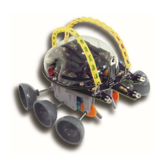
Thank you for buying the KSR4! Read this manual carefully before bringing the device into use.
The KSR4 works just like an A.I. robot. It never fails to find its way out of a maze. The Escape Robot uses 3 infrared
emitting diodes and 1 infrared receiving module to send and receive signals and detect obstacles. The Escape
Robot's built-in microprocessor enables it to "think" on its own: it gathers and processes information about its
environment, which enables it to avoid any obstacle. The Escape Robot moves around on 6 legs.
The Kit comes complete with 2 sets of differently designed legs, which move in their own distinct way. Fun and
excitement are guaranteed.
The KSR4 requires four 1.5Vdc AAA-batteries (not included).
Apart from the batteries, you will also need a pair of long-nose pliers, a soldering iron, a diagonal cutter, a
screwdriver, a soldering iron and a length of solder wire.
2. Electronic Parts List
1. resistor: 4x 10Ω (brown/black/black/gold)
2x 16Ω (brown/blue/black/gold)
1x 39Ω (orange/white/black/gold)
1x 100Ω (brown/black/brown/gold)
5x 1K (brown/black/red/gold)
1x 10K (brown/black/orange/gold)
4x 22K (red/red/orange/gold)
2. ceramic capacitor: 2x type 30, 1x type 103, 3x type 104, 1x type 224
3. electrolytic capacitor 100uf (1x)
4. IR LED 5mm, clear (3x)
5. LED 5mm, red (1x)
6. buzzer (1x)
7. Zener diode 3.9V (1x)
8. oscillator 4MHz (1x)
9. transistor: 7x 8050, 4x 8550, 1x 9013, 4x C945
10. LED holder (3x)
11. IC: 1 x type 78P156 (1602BP)
12. IC socket (1x)
13. Battery connector (1x)
14. IR receiving module (1x)
15. battery holder (1x)
16. pin (4x)
17. slide switch (1 x)
18. connector with wire: 1 x yellow, 1 x green,
1 x orange, 1 x blue
19. PCB (1 x)
3. Mechanical Parts List
1. 2x screw P13 (3x6mm)
2. 4x screw P14 (3x6mm)
3. 2x hosepipe P18
4. 2x nut P16 (M3)
5. 2x hex post P15 (10mm)
6. 1x body P17
KSR4
KSR4 – "ESCAPE" ROBOT KIT
Fig. 1
1
VELLEMAN
Advertisement
Table of Contents

Related Manuals for Velleman KSR4


Summary of Contents for Velleman KSR4
- Page 1 Thank you for buying the KSR4! Read this manual carefully before bringing the device into use. The KSR4 works just like an A.I. robot. It never fails to find its way out of a maze. The Escape Robot uses 3 infrared emitting diodes and 1 infrared receiving module to send and receive signals and detect obstacles.
- Page 2 M1 (+/-) pins (fig.1 #16) M2 (+/-) Mount the LED, the IR LEDs and the IC: Fig. 3 Part ID Description Quantity LED1 LED 5mm (red) LED2/3/4 IR LED 5mm (clear) + LED holder 3 + 3 REMARK: KSR4 VELLEMAN...
-
Page 3: Gearbox Assembly
C: protection plates (4) for corner wheel/leg gears D: gear brackets (2) for corner wheel/leg gears E: gear brackets (2) for corner wheel/leg gears F: motor mounting bracket (1) G: top plate (1) H: wheels (6) I: legs (6) J: rubber feet for legs (6) KSR4 VELLEMAN... - Page 4 Assembly ODER KSR4 VELLEMAN...
-
Page 5: Mechanical Assembly
2. Fix the PCB to the gearbox and put the wires through the holes at the back of the device. Fig. 8 3. Attach the body to the device and put the wires through the hosepipes: Fig. 9 KSR4 VELLEMAN... -
Page 6: Wiring Diagram
4. Connect the wires to the pins on the M-terminals. Fig. 10 5. Finished product Fig. 11 5. Wiring Diagram Fig. 12 KSR4 VELLEMAN... -
Page 7: Operation
6. Operation Put the switch in the “ON”-position. LED1 is lit, the device emits 3 beeps and the KSR4 starts walking. The emitting diodes LED2, LED3 and LED4 send signals in sequence in order to detect obstacles. When an obstacle is detected, the received signal is sent to the receiving module which will then instruct the robot to take evasive action: a) When the emitting diode to the right detects an obstacle, you will hear a single beep. - Page 8 De Kit wordt geleverd met 2 verschillende sets poten, die elk op een verschillende manier bewegen. Plezier verzekerd! De KSR4 werkt op vier AAA-batterijen van 1.5V (niet meegeleverd). Behalve de batterijen heeft u ook een bektang, een zijkniptang, een schroevendraaier, een soldeerijzer en soldeerdraad nodig.
- Page 9 Monteer de LED, de IR LEDs en de IC: Onderdeel Beschrijving Hoev. LED1 LED 5mm (rood) LED2/3/4 IR LED 5mm (helder) + LED houder 3 + 3 Opmerking: Monteer de IR ontvangstmodule: (zie fig. 3 blz. 3) Onderdeel Beschrijving Hoev. IR_RX_MOD IR ontvangstmodule(fig.1 #14) KSR4 VELLEMAN...
-
Page 10: Mechanische Montage
(zie fig.12 blz. 6) 6. Bediening Plaats de schakelaar in de “ON”-stand. LED1 gaat branden, het toestel biept 3 x en de KSR4 begint te lopen. De zenddiodes LED2, LED3 en LED4 zenden achtereenvolgens signalen uit om hindernissen te ontdekken. Wanneer... -
Page 11: Problemen En Oplossingen
Probeer de ideale positie te vinden voor de IR ontvangstmodule. 3. Smeer wat fijne machineolie op de assen van de tandwielen als de KSR4 niet soepel loopt. De specificaties en de inhoud van de handleiding kunnen worden gewijzigd zonder voorafgaande kennisgeving. -
Page 12: Montage
Montez le support de CI, le connecteur d'alimentation, la glissière, le buzzer et les broches. Pièce Description Qté support de CI (fig.1 #12) BAT. connecteur d'alimentation (fig.1 #13) glissière (fig.1 #17) buzzer (fig.1 #6) M1 (+/-) broches (fig.1 #16) M2 (+/-) KSR4 VELLEMAN... -
Page 13: Montage Mécanique
3. Assemblez le boîtier et faites passer les fils par les tresses (voir fig. 9 à la p. 5) 4. Reliez les fils aux broches des connexions M (voir fig. 10 à la p. 6). 5. Produit fini (voir fig.11 à la p. 6) KSR4 VELLEMAN... -
Page 14: Opération
2. La sensibilité peut être affectée par la puissance diminuante des piles ou un changement d'environnement. Cherchez la position idéale pour le module de réception IR. 3. Lubrifiez les axes des pignons avec un peu d'huile de graissage fine si les mouvements de votre KSR4 ne sont pas souples. - Page 15 Luego, monte el diodo Zener, los condensadores, los transistores y el oscilador: Pieza Descripción Cantidad diodo Zener 3.9V C2/3 condensador cerámico 30 condensador cerámico 103 condensador cerámico 104 condensador cerámico 224 condensador electrolítico 100uf Q5/6/7/8 transistor 8550 transistor 9013 Q1/3/4/9/10/11/12 transistor 8050 Q13/14/15/16 transistor C945 XTAL oscilador 4MHz KSR4 VELLEMAN...
- Page 16 E: placas de montaje para los piñones que se montan en las esquinas (2) F: placa de montaje para motores (1) G: placa superior (1) H: ruedas (6) I: patas (6) J: pie de goma (6) Montaje: véase las figuras en la lista p. 4. KSR4 VELLEMAN...
-
Page 17: Solución De Problemas
IR. 3. Engrase los ejes de los engranajes con un poco de aceite de máquina fino si el KSR4 no se mueve con agilidad. Se pueden modificar las especificaciones y el contenido de este manual sin previo aviso. - Page 18 4. Montage a) Montage der Leiterplatte Montieren Sie zuerst die Widerstände. Die Namen der Komponenten stehen auf der Leiterplatte. Teil Beschreibung Farbcode Menge braun/schwarz/braun/gold 100Ω R11/12/13/14 braun/schwarz/schwarz/gold 10Ω R3/4 braun/blau/schwarz/gold 16Ω orange/weiß/schwarz/gold 39Ω R5/7/8/9/10 braun/schwarz/rot/gold braun/schwarz/orange/gold R2/6/16/17 rot/rot/orange/gold KSR4 VELLEMAN...
- Page 19 P3: Schraube (2x10mm) x 4 P9: Getrieberad 8T (weiß) x 2 P4: Mutter (M2) x 4 P10: Zahnrad 48/18T (weiß) x 2 P5: Blechschraube (3x7mm) x 34 P11: Zahnrad 44/18T (weiß) x 4 P6: Ring x 6 P12: transparentes Röhrchen x 2 KSR4 VELLEMAN...
-
Page 20: Probleme Und Lösungen
(siehe Abb.12 Seite 6) 6. Bedienung Stellen Sie den Schalter in die “ON”-Position. LED1 wird brennen, das Gerät piepst 3x und der KSR4 fängt an zu laufen. Die Sendedioden LED2, LED3 und LED4 senden nacheinander Signale um Hindernisse zu entdecken. Wenn ein Hindernis detektiert wird, wird das empfangene Signal an das Empfangsmodul gesendet und welches den Befehl zum Ausweichen des Hindernisses gibt.
Need help?
Do you have a question about the KSR4 and is the answer not in the manual?
Questions and answers