Table of Contents
Advertisement
Quick Links
PROFESSIONAL MEDICAL PRODUCTS
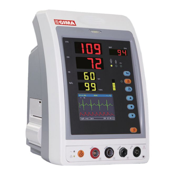
GIMA VITAL-SNET MONITOR
User Manual
ATTENTION: The operators must carefully read and completely understand
the present manual before using the product
z
0123
Gima S.p.A. - Via Marconi, 1 - 20060 Gessate (MI) Italy
Italia: tel. 199 400 401 - fax 199 400 403
Export: tel. +39 02 953854209/221/225 fax +39 08 95380056
gima@gimaitaly.com - export@gimaitaly.com
www.gimaitaly.com
Fabbricante/Manufacturer:
Shenzhen Creative Industry Co., Ltd. 2/F Block 3 Nanyou Tian'an Industry Town
518054 Shenzhen, GD - P.R.C.
Shanghai International Trading Corp. GmbH (Hamburg)
Eiffestrasse 80, 20537 Hamburg - Germany
Advertisement
Table of Contents

Related Manuals for Gima VITAL-SNET


Summary of Contents for Gima VITAL-SNET
- Page 1 Gima S.p.A. - Via Marconi, 1 - 20060 Gessate (MI) Italy Italia: tel. 199 400 401 - fax 199 400 403 Export: tel. +39 02 953854209/221/225 fax +39 08 95380056 gima@gimaitaly.com - export@gimaitaly.com PROFESSIONAL MEDICAL PRODUCTS www.gimaitaly.com GIMA VITAL-SNET MONITOR...
- Page 2 This Manual is written and compiled in accordance with the IEC 60601-1 Medical electrical equipment Part1: General requirements for safety and MDD 93/42/EEC. It complies with both international and enterprise standards and is also approved by State Technological Supervision Bureau. The Manual is written for the current PC-900 Vital Signs Monitor. The Manual describes, in accordance with the Vital Signs Monitor’s features and requirements, main structure, functions, specifications, correct methods for transportation, installation, usage, operation, repair, maintenance and storage, etc.
- Page 3 Instructions to User Dear Users, Thank you very much for purchasing our product. Please read the following information very carefully before using this device. Read these instructions carefully before using this monitor. These instructions describe the operating procedures to be followed strictly. Failure to follow these instructions can cause monitoring abnormity, equipment damage and personal injury.
- Page 4 obtained. Dispose of the device and its accessories, the local law should be followed. -III-...
-
Page 5: Table Of Contents
Table of Contents CHAPTER 1 OVERVIEW ....................1 1.1 F ............................1 EATURES 1.2 P ......................1 RODUCT AME AND ODEL 1.3 I ..........................1 NTENDED 1.4 C ..........................1 ONFORMATION 1.5 S ......................2 YMBOLS ON THE ONITOR CHAPTER 2 OPERATING PRINCIPLE................3 2.1 O ........................ - Page 6 4.5 S ........................21 ETUP CREEN 4.5.1 ECG and Temperature Setup ....................22 4.5.2 SpO Setup .......................... 23 4.5.3 NIBP Setup .......................... 24 4.5.4 Nurse Call..........................25 4.5.5 System Setup........................26 4.5.6 Patient Info ........................... 27 4.5.7 Date/Time..........................27 4.5.8 Recover Default Settings ..................... 27 4.6 P ........................
- Page 7 9.1 S ......................37 ERVICE AND XAMINATION 9.1.1 Daily Examination ........................ 37 9.1.2 Routine Maintenance ......................37 9.1.3 Battery Maintenance......................37 9.1.4 Service ..........................38 9.2 C ................. 38 LEANING TERILIZATION AND ISINFECTION 9.3 C ............39 LEANING TERILIZATION AND ISINFECTION OF CCESSORIES 9.4 S...
-
Page 8: Chapter 1 Overview
Chapter 1 Overview 1.1 Features Blood Pressure, SpO and Pulse Rate are displayed by big, bright digital LEDs; ECG waveform, SpO plethysmogram and system parameters are displayed on dot matrix LCD screen; with hardware and software over-pressure Accurate NIBP measurement protection;... -
Page 9: Symbols On The Monitor
1.5 Symbols on the Monitor Adult Patient Waveform Freeze Pediatric Patient Pulse sync indicator Neonatal Patient Setup Menu NIBP Start/Cancel AC Power Alarm Silence DC Power Print Type BF applied part Type CF applied part with defibrillator protection Warning, refer to User Manual. Down Equal potential terminal ECG Lead Selection... -
Page 10: Chapter 2 Operating Principle
Chapter 2 Operating Principle 2.1 Overall Structure The overall structure of the monitor is shown in Fig. 2.1. Figure 2.1 PC-900 Vital Signs Monitor is module designed product; it consists of ECG/TEMP module (optional), NIBP module (optional), SpO module (optional), main control unit, printer module (optional), display panel, and power supply block etc. -
Page 11: Chapter 3 Installation And Connection
Chapter 3 Installation and Connection 3.1 Appearance 3.1.1 Front Panel Figure 3.1 Front panel illustration Description: Alarm indicator Indicator Alarm Level Alarm Event Red flashing High priority alarm Exceeding the limits, low battery voltage Orange Medium priority alarm Leads or probe off Green light Normal... - Page 12 SYS: display systolic pressure value DIA: display diastolic pressure value. MAP: Display mean arterial pressure or measuring time of the latest group of NIBP measurement; they will be displayed alternately. The format of NIBP measuring time is “hh:mm”. If the tourniquet is in use, the cuff pressure will be diplayed here. Note: two formats to display NIBP value: “×××mmHg”...
-
Page 13: Side Panel
Down: shift cursor backward/downward Display: shift LCD display modes Waveform Freeze: freeze the current displayed waveform. ECG Lead Selection: select ECG leads among I, II, III, aVR, aVL, aVF and V. : AC Power indicator : DC Power indicator AC Power DC Power indicator Descriptions indicator... -
Page 14: Rear Panel
3.1.3 Rear Panel Figure 3.2 Rear Panel Introduction to the rear panel: 1 Handle Nameplate “FUSE T3.15 A”: Fuse holder. Fuse specification: T3.15AL/250V 5 20mm. “AC100~250V” : AC power supply socket Loudspeaker Mounting hole for hanging the monitor NET: serial communication port which is used to network with central monitoring system (optional);... -
Page 15: Installation
3.2 Installation 3.2.1 Opening the Package and Check 1. Open the package, take out the monitor accessories from the box carefully and place it in a safe stable and easy to watch position. 2. Open the accompanying document to sort the accessories according to the packing list. Inspect the monitor for any mechanical damages Check all the accessories for any scratch or deformity, especially on connector, wire and probe parts... -
Page 16: Sensor Placement And Connection
3.3 Sensor Placement and Connection 3.3.1 ECG Cable Connection ECG measurement is to collect the ECG signal via the ECG electrodes. Electrode connects the patient and the lead. The lead connects the monitor. The locations of the electrodes are very important for obtaining accurate ECG signals. - Page 17 electrode C3 (V3) The electrodes are placed in different places, the different lead forms will display. C4 (V4) C5 (V5) C6 (V6) Table 3-1 Safety Instructions for ECG Monitoring Use the same type electrode on a patient. If skin rash or other unusual symptom occurs, remove electrodes from patient.
-
Page 18: Blood Pressure Cuff Connection
3.3.2 Blood Pressure Cuff Connection 1. Select a cuff of appropriate size according to the age of the subject. Its width should be 2/3 of the length of the upper arm. The cuff inflation part should be long enough to permit wrapping 50-80% of the limb concerned. -
Page 19: Spo 2 Sensor Connection
Do NOT bind NIBP cuff on limbs with transfusion tube or intubations or skin lesion area, otherwise, damages may be caused to the limbs. Prior to use of the cuff, empty the cuff until there is no residual air inside it to ensure accurate measurement. -
Page 20: Temp Transducer Connection
Safety Introductions for SpO Monitoring Continuous use of finger clip SpO sensor may result in discomfort or pain, especially for those patients with microcirculatory problem. It is recommended that the sensor should NOT be applied to the same finger for over two hours. measuring position must be examined more carefully for some special patient. - Page 21 Figure 3.7 Loading and taking out printing paper -14-...
-
Page 22: Battery Installation
3.3.6 Battery Installation 1. Ensure that the monitor is not connected to AC power supply and the monitor is turned off. 2. Open the battery cover and place the battery in the direction as shown in Fig. 3.8 to insert the battery into any one of battery compartments. Do not insert battery with their polarities reversed. -
Page 23: Chapter 4 Operations
Chapter 4 Operations 4.1 Initial Monitoring Screen When the parameter configuration of monitor is “ECG+SpO +NIBP”, insert the ECG cable into the socket labeled “ECG” and attach the ECG leads to the electrodes placed on human body, once powered up, the LCD will display the initial monitoring screen, this is the default display screen as well. -
Page 24: Default Display Screen Description
prompt info area contains 3 segment of information: status or event indication at the left, patient ID number in the middle, real time clock at the right (also see Figure 4.1). 4.1.1 Default Display Screen Description Title area: ECG lead status and ECG waveform scale. “ECG”: indicate the current monitoring parameter is ECG. -
Page 25: Spo 2 Monitoring Screen
“ ” key: Alarm silence switch, press it to enable/disable alarm silence. “ ”/ “ ”key change ECG waveform scale. 4.2 SpO Monitoring Screen Short time press “ Display” key to shift the screen view to SpO monitoring screen, as shown in Figure 4.3. -
Page 26: Operation Instructions
Figure 4.4 Probe Off 4.2.2 Operation Instructions “ ” key: press this key to shift to next display view (SpO trend graph). “ ” key: Press it to print a trace of SpO plethysmogram, press it again to stop printing. “... -
Page 27: Operation Instructions
displayed in trend graph, so the user can move the cursor to inspect the SpO value at the given time. “SpO ”: indicate that the trend graph beside it is SpO trend. Let the cursor stay here and press“ ” key to confirm, then press “ ”... -
Page 28: Operation Instructions
Figure 4.6 NIBP List The first column is the date, the second column is NIBP measuring time, the third column is NIBP value, and the fourth column is pulse rate (measured by NIBP module). “SYS/DIA/MAP” indicates the value of “systolic pressure/diastolic pressure/mean arterial pressure”. 4.4.1 Operation Instructions On NIBP List screen, if NIBP measurement is more than 6 groups, press “... -
Page 29: Ecg And Temperature Setup
There are 8 functional groups for setting parameters: “ECG TEMP, SpO , NIBP, Nurse Call, System, Patient Info, Date/Time and Default” on the Setup Menu Screen. 1. Press“ ” key or “ ” key to shift cursor to corresponding functional group setting. 2. -
Page 30: Spo 2 Setup
4.5.2 SpO Setup Figure 4.9 SpO Setup Screen Screen Description: “SpO ”: SpO alarm switch; “ ” indicates SpO alarm is on; “ ” indicates SpO alarm is off. “SpO Hi”: high limit of SpO alarm; range: “1~100”. “SpO Lo”: low limit of SpO alarm;... -
Page 31: Nibp Setup
4.5.3 NIBP Setup Figure 4.10A NIBP Setup Figure 4.10B Tourniquet Setup NIBP Setup Screen Description: “SYS ”: systolic pressure alarm switch; “ ” indicates systolic pressure alarm is on; “ ” indicates systolic pressure alarm is off. “SYS Hi”: high limit of systolic pressure alarm; range: “32~250” mmHg. “SYS Lo”: low limit of systolic pressure alarm;... -
Page 32: Nurse Call
for neonates: preset range: 70~100mmHg, default value: “90” mmHg; for infants: preset range: 80~130 mmHg, default value: “110” mmHg; for adults: preset range: 80~180mmHg, default value: “140” mmHg. If the pressure drops down slowly under 10mmHg compared with the preset value due to little air leakage in the pneumatic system when time passes by, the monitor will re-inflate to maintain the cuff pressure close to the preset pressure value. -
Page 33: System Setup
“Source”: three kinds of alarm sources can trig the nurse call: high level alarm, medium level alarm and low level alarm (multi-optional). If you don’t make choice, nurse call signal will not be sent out. “Duration”: two options “pulse” or “continuous” output modes are available; “continuous”: the continuous mode of output means the nurse call signal will keep until the selected alarm source(es) disappear, i.e. -
Page 34: Patient Info
4.5.6 Patient Info Figure 4.13 Patient Info Screen Screen Description: “ID”: change or set current patient’s ID number, 0~100 adjustable; “category”: change or set the category of current patient; three options “adult”, “pediatric” and “neonate”, the default is “adult”. Note: If the patient ID is changed, all the history data will be cleared, that means SpO trend graph, HR trend graph and NIBP list will become empty. -
Page 35: Power Saving Mode
4.6 Power Saving Mode On the initial display screen, you can make the monitor stay in power saving mode for power saving. Short time press power button to shift screen to “Power Saving Mode” display screen, as shown in Figure 4.12. Figure 4.12 Power Saving Mode Press “... -
Page 36: Temp Monitoring
12. Frequency response: 0.5 Hz 40Hz( 5.2 TEMP Monitoring 1. TEMP measuring range: 25.0 ~45.0 2. TEMP measuring accuracy: ±0.2 3. TEMP responding time: ≤150s 5.3 NIBP Monitoring 1. Measuring method: Oscillometric Technique 2. Pneumatic pressure measuring range: 0 mmHg~300mmHg 3. -
Page 37: Data Recording
5.6 Data Recording 1. Sensitivity selection tolerance: ±5% 2. Recording speed: 25mm/s 5.7 Other Technical Specifications 1. AC power supply voltage: 100~250VAC 2. AC power frequency: 50/60 Hz 3. Fuse specification: T3.15AL/250V 5 20mm. 4. Internal power supply: 12VDC (rechargeable) 5. -
Page 38: Chapter 6 Packaging And Accessories
Chapter 6 Packaging and Accessories 6.1 Packaging The product is packed in high quality corrugated cartons with foam inside to protect the equipment against damage in the shipping and handling process. Weight: Details see the indication on the outer package. Dimension: 360(L)×320(W)×410(H) (mm) 6.2 Accessories (1) ECG cable with lead wire... -
Page 39: Chapter 7 Working Principle
Chapter 7 Working Principle 7.1 How to Obtain High Quality ECG and Accurate Heart Rate Value The electrocardiogram (ECG or EKG) is primarily a tool for evaluating the electrical events within the heart. The action potentials of cardiac-muscle cells can be viewed as batteries that cause charge to move throughout the body fluids. -
Page 40: Points To Be Noted In Nibp Measurement
methodologies, such as the Korotkoff Sound Method and oscillating method. The Korotkoff Sound Method is used as a conventional way, whereby stethoscope is used to measure the blood pressure. By the oscillating method, an inflation pump will fill the air, and release it slowly. A computer will record change of the cuff pressure when the air is released. -
Page 41: Clinical Limitations
4. The measures should be taken at appropriate intervals. Continuous measurement at too short intervals may lead to pressed arm, reduced blood flow and lower blood pressure, and resulting inaccurate measure of blood pressure. It is recommended the measure be taken at intervals of more than two minutes. -
Page 42: Points To Be Noted In Spo And Pulse Measuring
7.3.2 Points to be noted in SpO and Pulse Measuring 1. The finger should be properly placed (see the attached illustration of this instruction manual), or else it may cause inaccurate measurement result. 2. Make sure that capillary arterial vessel beneath the finger is penetrated through by red and infrared lights. -
Page 43: Chapter 8 Troubleshooting
Chapter 8 Troubleshooting 8.1 No Display on the Screen Shut down the machine and unplug the power. Use a universal meter to check if the outlet has proper voltage, if the power cable is in good condition, and if the power cable is properly connected with this apparatus or outlet. -
Page 44: Chapter 9 Maintenance
Chapter 9 Maintenance 9.1 Service and Examination 9.1.1 Daily Examination Before using the monitor, the checks below should be carried out: Check the monitor for any mechanical damage; Inspect the exposed parts and the inserted parts of all the leads, and the accessories; Examine all the functions of the monitor that are likely to be used for patient monitoring, and ensure that it is in good working condition;... -
Page 45: Service
After battery ageing phenomenon occurring, to avoid explosion risk do NOT throw the battery into fire. Do not hit or strike it with force; Do not use this battery on other devices; Do not use this battery below -10 or above 40 ; Dispose of the battery, the local law should be followed. -
Page 46: Cleaning, Sterilization And Disinfection Of Accessories
Do not put any parts of the monitor in the liquid. Do not pour the disinfector on its surface while sterilization. 9.3 Cleaning, Sterilization and Disinfection of Accessories It is recommended to use a cloth dampened with isopropyl alcohol 70%, a 10% aqueous solution of sodium hypochlorite (bleach), a 2% gluteraldegyde solution, ammonia, mild soap or disinfectant spray cleaner to clean the accessories (including sensor, ECG cable and plugs). -
Page 47: Appendix
Appendix Prompt information explanations Mute C-D: XXX seconds Alarm silence count down: XXX seconds NIBP C-D: XXX seconds NIBP auto measuring cycle count down: XXX seconds TOUR C-D: XXX Tourniquet alert count down: XXX seconds Probe off probe fells off PR over limit PR value exceeds the high/low alarm limit over limit... -
Page 48: Default Alarming Values Of All Parameters And Setup Range
Default Alarming Values of All Parameters and Setup Range Default Mode Alarm range Adult Pediatric Neonate Parameter High (21~250) bpm 180bpm 200bpm 220bpm (20~249) bpm 40bpm 50bpm 50bpm 32~250 High 180mmHg 130mmHg 110mmHg 30~248 60mmHg 50mmHg 50mmHg 22~232 High 120mmHg 90mmHg 90mmHg 20~230... - Page 49 The warranty is valid for 12 months from the date of supply of GIMA. During the period of validity of the warranty, GIMA will repair and/or replace free of charge all the defected parts due to production reasons. Labor costs and personnel traveling expenses and packaging not included.
Need help?
Do you have a question about the VITAL-SNET and is the answer not in the manual?
Questions and answers