Puls YR20.246 Manual
24-28v, 20a, dual redundancy module
Hide thumbs
Also See for YR20.246:
- Installation manual (2 pages) ,
- Instruction manual (2 pages) ,
- Installation manual (2 pages)
Table of Contents
Advertisement
Quick Links
Y-Series
G
D
ENERAL
ESCRIPTION
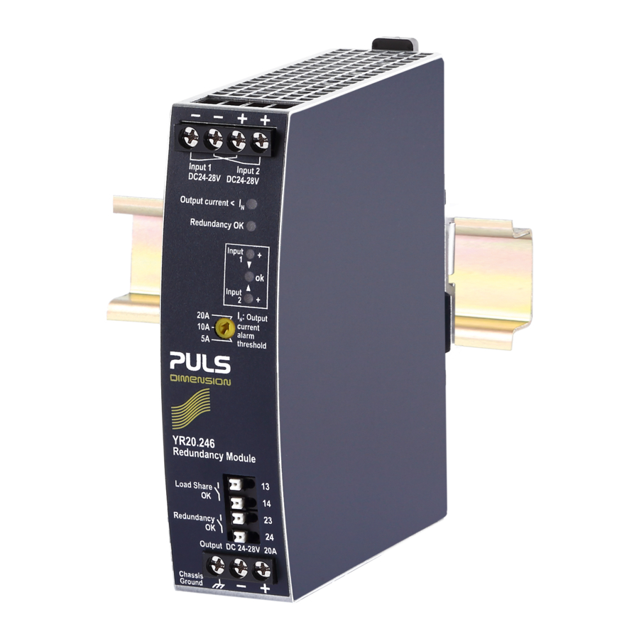
The YR20.246 is a redundancy module for building
redundant power supply systems. It is equipped with
two input channels and one output. The two inputs are
decoupled by MOSFET technology.
The device is equipped with an automated load sharing
feature, which can compensate a small voltage
imbalance between the power supplies connected to
the inputs in order to achieve an even current share. It
also monitors the function of the redundancy circuitry
and provides a signal in case of a failure or a high
output current, which could prevent redundancy if one
power supply fails. If this feature is not required the
YR20.242 is available.
The redundancy utilizes MOSFETs instead of diodes for
the decoupling of the two input channels. This reduces
the heat generation and the voltage drop between
input and output. The redundancy module does not
require an additional auxiliary voltage.
Due to the low power losses, the unit is very slender and
only requires 32mm width on the DIN-rail. Large
connection terminals allow for a safe and fast
installation. The large international approval package
makes this unit suitable for nearly every application.
O
N
RDER
UMBERS
Redundancy
YR20.246
Module
Accessory
ZM11.SIDE
Jul. 2017 / Rev. 1.4 DS-YR20.246-EN
after a 5 minutes run-in time unless otherwise noted.
Side mount bracket
All parameters are typical values specified at 24V, 20A output current, 25°C ambient and
www.pulspower.com Phone +49 89 9278 0
24-28V, 20A, D
UAL
M
R
OSFET
EDUNDANCY
For 1+1 Redundancy with Automated Load Sharing
Dual Input with Single Output
Redundancy OK Signal Included which Reports the Loss
of Redundancy
160% (32.5A) Peak Load Capability
Reverse Input Polarity Protection
Full Power Between -40°C and +70°C
Width only 32mm
Rugged Metal Housing
Easy Wiring:
Distribution Terminal for Negative Pole Included
S
-
D
HORT
FORM
Input voltage
DC 24-28V
Input voltage range 18-35Vdc
Input current
2x 0-12A
Output current
0-24A
Input to output
voltage drop
Power losses
Temperature range
Dimensions
32x124x117mm WxHxD
Weight
310g, 0.69lb
*)
Currents at voltages below 6V
**) Depending on load share function
M
ARKINGS
IND. CONT. EQ.
UL 508
IECEx
ATEX
Germany
YR20.246
R
M
EDUNDANCY
ODULE
M
ODULE
ATA
±25%
ambient <+45°C
2x 0-10A
ambient <+70°C
ambient <+45°C
0-20A
ambient <+70°C
max. 26A
in overload
short circuit mode
0.1-0.5V
**)
input: 2x5A
**)
0.2-0.5V
input: 2x10A
1.7W
at no load
**)
2.6-4.7W
input: 2x5A
5.6-8.7W
**)
input: 2x10A
-40°C to +70°C operational
Class I Div 2
UL 60950-1
planned
Marine
planned
*)
or
1/19
Advertisement
Table of Contents

Related Manuals for Puls YR20.246


Summary of Contents for Puls YR20.246
- Page 1 Easy Wiring: Distribution Terminal for Negative Pole Included ENERAL ESCRIPTION HORT FORM The YR20.246 is a redundancy module for building Input voltage DC 24-28V ±25% redundant power supply systems. It is equipped with Input voltage range 18-35Vdc two input channels and one output. The two inputs are...
-
Page 2: Table Of Contents
IN 1 IN 2 achieve a 10A redundant system. Load Jul. 2017 / Rev. 1.4 DS-YR20.246-EN All parameters are typical values specified at 24V, 20A output current, 25°C ambient and after a 5 minutes run-in time unless otherwise noted. 2/19 www.pulspower.com Phone +49 89 9278 0... -
Page 3: Intended Use
Increase the side clearance to 15mm in case the adjacent device is a heat source (e.g. another power supply). See chapter 21.4 for other allowed clearances when used with the PULS DIMENSION series in a 1+1 redundant configuration. -
Page 4: Input And Output Characteristics
2x10A 2x12.5A Input: Voltage Drop Jul. 2017 / Rev. 1.4 DS-YR20.246-EN All parameters are typical values specified at 24V, 20A output current, 25°C ambient and after a 5 minutes run-in time unless otherwise noted. 4/19 www.pulspower.com Phone +49 89 9278 0... -
Page 5: Power Losses
100 hours if 10 000 units are installed in the field. However, it can not be determined if the failed unit has been running for 50 000h or only for 100h. Jul. 2017 / Rev. 1.4 DS-YR20.246-EN All parameters are typical values specified at 24V, 20A output current, 25°C ambient and after a 5 minutes run-in time unless otherwise noted. -
Page 6: Terminals And Wiring
Chassis Ground Input 2 Control Jul. 2017 / Rev. 1.4 DS-YR20.246-EN All parameters are typical values specified at 24V, 20A output current, 25°C ambient and after a 5 minutes run-in time unless otherwise noted. 6/19 www.pulspower.com Phone +49 89 9278 0... -
Page 7: Front Side And User Elements
See chapter 11 for detailed description. See chapter 10 for contact ratings. Jul. 2017 / Rev. 1.4 DS-YR20.246-EN All parameters are typical values specified at 24V, 20A output current, 25°C ambient and after a 5 minutes run-in time unless otherwise noted. -
Page 8: Redundancy Ok" Relay Contact
Isolation voltage See dielectric strength table in section 16. Jul. 2017 / Rev. 1.4 DS-YR20.246-EN All parameters are typical values specified at 24V, 20A output current, 25°C ambient and after a 5 minutes run-in time unless otherwise noted. -
Page 9: Automated Load Sharing
"Load Share OK" contact is open "Load Share OK" contact is closed The active load share feature of the YR20.246 has a similar effect and benefit as the feature “Parallel Mode” (soft output characteristic), which is available on larger PULS power supplies. -
Page 10: 12. Emc
The internal auxiliary supply is generated with a boost converter. The switching frequency varies from 140kHz to 500kHz depending on the input voltage. Jul. 2017 / Rev. 1.4 DS-YR20.246-EN All parameters are typical values specified at 24V, 20A output current, 25°C ambient and after a 5 minutes run-in time unless otherwise noted. -
Page 11: Environment
70°C 2000 4000 6000m Jul. 2017 / Rev. 1.4 DS-YR20.246-EN All parameters are typical values specified at 24V, 20A output current, 25°C ambient and after a 5 minutes run-in time unless otherwise noted. 11/19 www.pulspower.com Phone +49 89 9278 0... -
Page 12: Protection Features
> 2mA > 2mA Load Share OK, Redundancy OK Jul. 2017 / Rev. 1.4 DS-YR20.246-EN All parameters are typical values specified at 24V, 20A output current, 25°C ambient and after a 5 minutes run-in time unless otherwise noted. 12/19 www.pulspower.com Phone +49 89 9278 0... -
Page 13: Approvals
, 2007 regarding the Registration, Evaluation, Authorisation and Restriction of Chemicals (REACH) Jul. 2017 / Rev. 1.4 DS-YR20.246-EN All parameters are typical values specified at 24V, 20A output current, 25°C ambient and after a 5 minutes run-in time unless otherwise noted. -
Page 14: Physical Dimensions And Weight
See chapter 2 Fig. 19-1 Front view Fig. 19-2 Side view Jul. 2017 / Rev. 1.4 DS-YR20.246-EN All parameters are typical values specified at 24V, 20A output current, 25°C ambient and after a 5 minutes run-in time unless otherwise noted. -
Page 15: Accessories
RACKET This bracket is used to mount the YR20.246 redundancy module sideways with or without utilizing a DIN-Rail. The two aluminum brackets and the black plastic slider of the unit have to be detached, so that the steel brackets can be mounted. -
Page 16: Application Notes
Losses 2.5A 7.5A 12.5A Jul. 2017 / Rev. 1.4 DS-YR20.246-EN All parameters are typical values specified at 24V, 20A output current, 25°C ambient and after a 5 minutes run-in time unless otherwise noted. 16/19 www.pulspower.com Phone +49 89 9278 0... -
Page 17: Recommendations For Redundancy
Redundancy Supply Supply Module 1+1 redundancy application with maximum 12A output current. The power supplies are from the PULS DIMENSION series. Output Input Input The redundancy module is placed between the two power supplies. Load The output voltage is set to the same level on both power supplies. -
Page 18: 1+1 Redundancy Up To 10A
24-28V, 20A, D Y-Series EDUNDANCY ODULE 21.5. 1+1 R EDUNDANCY UP TO 1+1 Redundancy up to 10A requires two 10A power supplies and one YR20.246 redundancy module. Fig. 21-5 Wiring diagram, 1+1 Redundancy, 10A output current Load Share Output Output... -
Page 19: Mounting Orientations
Orientation E (Horizontal ccw) Ambient Temperature 70°C Jul. 2017 / Rev. 1.4 DS-YR20.246-EN All parameters are typical values specified at 24V, 20A output current, 25°C ambient and after a 5 minutes run-in time unless otherwise noted. 19/19 www.pulspower.com Phone +49 89 9278 0...
Need help?
Do you have a question about the YR20.246 and is the answer not in the manual?
Questions and answers