Table of Contents
Advertisement
Quick Links
Y-Series
G
D
ENERAL
ESCRIPTION
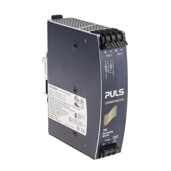
The YR2.DIODE is a redundancy module, which can be
used to build 1+1 and N+1 redundant systems. It is
equipped with two input channels, which can be
connected to power supplies with up to 10A output
current and one output, which can carry nominal
currents up to 20A. The module is suitable for power
supplies with constant current overload behavior as well
as any kind of "Hiccup" overload behavior.
The YR2.DIODE is the perfect solution to use in a
redundant system, if the power supply itself is equipped
with a DC-OK signal (e.g.: DIMENSION Q-Series). In
addition to the YR2.DIODE is the YRM2.DIODE which
has a monitoring circuitry included. LEDs and relay
contacts signal when one of the two DC-input voltages
is not in range due to a non-functioning power supply.
Another interesting application for this diode module is
to separate sensitive loads from non-sensitive loads. This
avoids the distortion of the power quality for the
sensitive loads which can cause controller failures.
Unique quick-connect spring-clamp terminals allow a
safe and fast installation and a large international
approval package for a variety of applications makes
this unit suitable for nearly every situation.
O
N
RDER
UMBERS
Redundancy
YR2.DIODE
Module
Accessory
ZM1.WALL
ZM11.SIDE
Apr. 2014 / Rev. 1.4 DS-YR2.DIODE-EN
All parameters are specified at 24V, 20A output current, 25°C ambient and after a 5 minutes run-in time unless otherwise noted
DC12-48V (120V), 20A, D
12-48V (120V)
Standard unit
Wall/ panel mount
bracket
Side mount bracket
www.pulspower.com Phone +49 89 9278 0
UAL
R
M
EDUNDANCY
ODULE
Cost Effective Solution to Build Redundant Systems
Dual Input with Single Output
Two Diodes (Common Cathode)
DC12-48V (120V) ±25% Wide-range Input
Full Power Between -40°C and +60°C
Width only 32mm
Rugged Metal Housing
Quick-connect Spring-clamp Terminals
Easy Wiring:
Distribution Terminal for Negative Pole Included
3 Year Warranty
S
-
D
HORT
FORM
Input voltage
DC 12-48V
DC 12-120V
Input voltage
9-60Vdc
range
9-150Vdc
Input current
2x 0-10A
2x 0-16A
Output current
0-20A
20-32A
25A
Input to output
typ. 0.78V
voltage drop
typ. 0.85V
typ. 0.85V
Power losses
typ. 0W
typ. 7.8W
typ. 8.5W
typ. 17W
Temperature range -40°C to +70°C
Derating
0.5A/°C
Dimensions
32x124x102mm
M
ARKINGS
IND. CONT. EQ.
UL 508
IECEx
ATEX
II 3G Ex nA IIC T4 Gc
Germany
YR2.DIODE
R
M
EDUNDANCY
ODULE
ATA
±25%
w/o restrictions
±25%
with restrictions
w/o restrictions
with restrictions
continuous
for 5 seconds
continuous
for 5 seconds
at cont. overload/
short circuit
input: 2x5A
input: 1x10A
input: 2x10A
at no load
input: 2x5A
input: 1x10A
input: 2x10A
operational,
+60 to +70°C
WxHxD
UL 60950-1
Class I Div 2
EMC, LVD
Marine
1/19
Advertisement
Table of Contents

Related Manuals for Puls Y Series


Summary of Contents for Puls Y Series
- Page 1 YR2.DIODE DC12-48V (120V), 20A, D Y-Series EDUNDANCY ODULE EDUNDANCY ODULE Cost Effective Solution to Build Redundant Systems Dual Input with Single Output Two Diodes (Common Cathode) DC12-48V (120V) ±25% Wide-range Input Full Power Between -40°C and +60°C Width only 32mm Rugged Metal Housing Quick-connect Spring-clamp Terminals Easy Wiring:...
-
Page 2: Table Of Contents
YR2.DIODE DC12-48V (120V), 20A, D Y-Series EDUNDANCY ODULE NDEX Page Page Intended Use ............3 15. Physical Dimensions and Weight ..... 13 Installation Requirements........3 16. Accessories ............14 Input and Output Characteristics .......4 17. Application Notes..........15 Power Losses............5 17.1. Recommendations for Redundancy..15 Lifetime Expectancy and MTBF......6 17.2. -
Page 3: Intended Use
YR2.DIODE DC12-48V (120V), 20A, D Y-Series EDUNDANCY ODULE 1. I NTENDED This redundancy module is designed for installation in an enclosure and is intended for the general use such as in industrial control, office, communication, and instrumentation equipment. This redundancy module can be used with any type of power supply as long as the maximum ratings are not exceeded. It is suitable for power supplies with constant current overload behavior as well as any kind of “Hiccup”... -
Page 4: Input And Output Characteristics
YR2.DIODE DC12-48V (120V), 20A, D Y-Series EDUNDANCY ODULE 3. I NPUT AND UTPUT HARACTERISTICS Number of inputs Number of outputs ±25% Input voltage nom. DC 12-48V The input circuitry must meet the SELV requirements stipulated by IEC/EN/UL 60950-1. Input voltage range 9-60Vdc ±25% Input voltage with restrictions... -
Page 5: Power Losses
YR2.DIODE DC12-48V (120V), 20A, D Y-Series EDUNDANCY ODULE Fig. 3-2 Input to output voltage drop when both inputs draw current (typical 1+1 redundant case, when the output voltages of the two units are equal or set into “parallel use” mode) Voltage Drop, typ. -
Page 6: Lifetime Expectancy And Mtbf
YR2.DIODE DC12-48V (120V), 20A, D Y-Series EDUNDANCY ODULE 5. L MTBF IFETIME XPECTANCY AND The redundancy module has two input channels which are completely independent from each other. Each control circuit, auxiliary voltage source, or other circuitry in the module are designed separately for each input. The dual input redundancy module can be considered as two single redundancy modules combined together in one housing. -
Page 7: Terminals And Wiring
YR2.DIODE DC12-48V (120V), 20A, D Y-Series EDUNDANCY ODULE 6. T ERMINALS AND IRING Input and output Type Bi-stable, quick-connect spring clamp terminals. IP20 Finger safe construction. Suitable for field- and factory installation. Shipped in open position. Solid wire 0.5-6mm Stranded wire 0.5-4mm American Wire Gauge 20-10 AWG... -
Page 8: Functional Diagram
YR2.DIODE DC12-48V (120V), 20A, D Y-Series EDUNDANCY ODULE 7. F UNCTIONAL IAGRAM Fig. 7-1 Functional diagram Input 1 Output Chassis Ground Input 2 8. F RONT IDE AND LEMENTS Fig. 8-1 Front side Output terminals Chassis ground terminal Connection of the chassis to ground is optional and not required since the unit fulfils the requirements according to protection class III. -
Page 9: Emc
YR2.DIODE DC12-48V (120V), 20A, D Y-Series EDUNDANCY ODULE 9. EMC The redundancy module is suitable for applications in industrial environment as well as in residential, commercial and light industry environment without any restrictions. A detailed EMC report is available on request. EMC Immunity According generic standards: EN 61000-6-1 and EN 61000-6-2 Electrostatic discharge... -
Page 10: Environment
YR2.DIODE DC12-48V (120V), 20A, D Y-Series EDUNDANCY ODULE 10. E NVIRONMENT Operational temperature -40°C to +70°C (-40°F to 158°F) Reduce output power above +60°C Output de-rating 0.5A/°C 60-70°C (140°F to 158°F), see Storage temperature -40 to +85°C (-40°F to 185°F) for storage and transportation Humidity 5 to 95% r.H. -
Page 11: Protection Features
YR2.DIODE DC12-48V (120V), 20A, D Y-Series EDUNDANCY ODULE 11. P ROTECTION EATURES Output over-current protection not included Reverse input polarity protection included unit does not start when input voltage is reversed Degree of protection IP 20 EN/IEC 60529 Penetration protection >... -
Page 12: Approvals
YR2.DIODE DC12-48V (120V), 20A, D Y-Series EDUNDANCY ODULE 14. A PPROVALS EC Declaration of Conformity The CE mark indicates conformance with the - EMC directive 2004/108/EC, - Low-voltage directive (LVD) 2006/95/EC and - RoHS directive 2011/65/EU. EC Declaration of Conformity The CE mark indicates conformance with the ATEX - ATEX directive 94/9/EC (Equipment and protection systems... -
Page 13: Physical Dimensions And Weight
YR2.DIODE DC12-48V (120V), 20A, D Y-Series EDUNDANCY ODULE 15. P HYSICAL IMENSIONS AND EIGHT Weight 290g / 0.64lb DIN-Rail Use 35mm DIN-rails according to EN 60715 or EN 50022 with a height of 7.5 or 15mm. The DIN-rail height must be added to the unit depth (102mm) to calculate the total required installation depth. -
Page 14: Accessories
YR2.DIODE DC12-48V (120V), 20A, D Y-Series EDUNDANCY ODULE 16. A CCESSORIES ZM1.WALL Wall mounting bracket This standard bracket is used to mount the YR40 redundancy module onto a flat surface without utilizing a DIN-Rail. Fig. 16-1 ZM1.WALL Wall mounting bracket Fig. -
Page 15: Application Notes
YR2.DIODE DC12-48V (120V), 20A, D Y-Series EDUNDANCY ODULE 17. A PPLICATION OTES 17.1. R ECOMMENDATIONS FOR EDUNDANCY Recommendations for the configuration of redundant power systems: • Use separate input fuses for each power supply. • Use three-phase power supplies to gain functional safety if one phase fails. •... -
Page 16: Example: N+1 Redundancy Up To 30A
YR2.DIODE DC12-48V (120V), 20A, D Y-Series EDUNDANCY ODULE 17.4. E : N+1 R XAMPLE EDUNDANCY UP TO N+1 Redundancy up to 30A requires four 10A power supplies and two YR2.DIODE redundancy modules. Fig. 17-2 Wiring diagram, n+1 Redundancy, 30A output current Failure Monitor IN 1... -
Page 17: Example: Redundancy For Controls
YR2.DIODE DC12-48V (120V), 20A, D Y-Series EDUNDANCY ODULE 17.6. E XAMPLE EDUNDANCY FOR ONTROLS The example shows a cost effective solution to get redundant power for a PLC or controller system. In many cases, two power supplies are used; one for the demanding loads and another one for the controls and sensitive loads. -
Page 18: Example: Decoupling Of Branches
YR2.DIODE DC12-48V (120V), 20A, D Y-Series EDUNDANCY ODULE 17.7. E XAMPLE ECOUPLING OF RANCHES Buffer energy supplied from a DC-UPS or buffer module is not wasted in “power branches”. Please note: Set output voltage of the power supply to a level that the buffer unit or DC-UPS will not start unexpected. Take the voltage drop of the YR2.DIODE into account. -
Page 19: Mounting Orientations
YR2.DIODE DC12-48V (120V), 20A, D Y-Series EDUNDANCY ODULE 17.9. M OUNTING RIENTATIONS Mounting orientations other than input terminals on the bottom and output on the top require a reduction in continuous output power or a limitation in the maximum allowed ambient temperature. Fig.
Need help?
Do you have a question about the Y Series and is the answer not in the manual?
Questions and answers