Table of Contents
Advertisement
Quick Links
Y-Series
G
D
ENERAL
ESCRIPTION
The YR20.246 is a redundancy module for building
redundant power supply systems. It is equipped with
two input channels and one output. The two inputs are
decoupled by MOSFET technology.
The device is equipped with an automated load sharing
feature, which can compensate a small voltage
imbalance between the power supplies connected to
the inputs in order to achieve an even current share. It
also monitors the function of the redundancy circuitry
and provides a signal in case of a failure or a high
output current, which could prevent redundancy if one
power supply fails. If this feature is not required the
YR20.242 is available.
The redundancy utilizes MOSFETs instead of diodes for
the decoupling of the two input channels. This reduces
the heat generation and the voltage drop between
input and output. The redundancy module does not
require an additional auxiliary voltage.
Due to the low power losses, the unit is very slender and
only requires 32mm width on the DIN-rail. Large
connection terminals allow for a safe and fast
installation. The large international approval package
makes this unit suitable for nearly every application.
O
N
RDER
UMBERS
Redundancy
YR40.246
Module
Accessory
ZM11.SIDE
May 2017 / Rev. 1.3 DS-YR20.246-EN
after a 5 minutes run-in time unless otherwise noted.
Side mount bracket
All parameters are typical values specified at 24V, 20A output current, 25°C ambient and
www.pulspower.com Phone +49 89 9278 0
24-28V, 20A, D
UAL
M
R
OSFET
EDUNDANCY
For 1+1 Redundancy with Automated Load Sharing
Dual Input with Single Output
Redundancy OK Signal Included which Reports the Loss
of Redundancy
160% (32.5A) Peak Load Capability
Reverse Input Polarity Protection
Full Power Between -40°C and +70°C
Width only 32mm
Rugged Metal Housing
Easy Wiring:
Distribution Terminal for Negative Pole Included
S
-
D
HORT
FORM
Input voltage
DC 24-28V
Input voltage range 18-35Vdc
Input current
2x 0-12A
Output current
0-24A
Input to output
voltage drop
Power losses
Temperature range
Dimensions
32x124x117mm WxHxD
Weight
310g, 0.69lb
*)
Currents at voltages below 6V
**) Depending on load share function
M
ARKINGS
IND. CONT. EQ.
UL 508
IECEx
ATEX
II 3G Ex nA IIC T4 Gc
planned
Germany
YR20.246
R
M
EDUNDANCY
ODULE
M
ODULE
ATA
±25%
ambient <+45°C
2x 0-10A
ambient <+70°C
ambient <+45°C
0-20A
ambient <+70°C
max. 26A
in overload
short circuit mode
0.1-0.5V
**)
input: 2x5A
**)
0.2-0.5V
input: 2x10A
1.7W
at no load
**)
2.6-4.7W
input: 2x5A
5.6-8.7W
**)
input: 2x10A
-40°C to +70°C operational
Class I Div 2
UL 60950-1
planned
Marine
planned
*)
or
1/19
Advertisement
Table of Contents

Subscribe to Our Youtube Channel
Related Manuals for Puls DIMENSION YR40.246


Summary of Contents for Puls DIMENSION YR40.246
- Page 1 YR20.246 24-28V, 20A, D Y-Series EDUNDANCY ODULE OSFET EDUNDANCY ODULE For 1+1 Redundancy with Automated Load Sharing Dual Input with Single Output Redundancy OK Signal Included which Reports the Loss of Redundancy 160% (32.5A) Peak Load Capability Reverse Input Polarity Protection Full Power Between -40°C and +70°C Width only 32mm Rugged Metal Housing...
-
Page 2: Table Of Contents
YR20.246 24-28V, 20A, D Y-Series EDUNDANCY ODULE NDEX Page Page U1. Intended Use ............3 16. Dielectric Strength..........12 Installation Requirements........3 17. Approvals ............13 Input and Output Characteristics .......4 18. RoHS, REACH and Other Fulfilled Standards .. 13 Power Losses............5 19. -
Page 3: U1. Intended Use
Increase the side clearance to 15mm in case the adjacent device is a heat source (e.g. another power supply). See chapter 21.4 for other allowed clearances when used with the PULS DIMENSION series in a 1+1 redundant configuration. -
Page 4: Input And Output Characteristics
YR20.246 24-28V, 20A, D Y-Series EDUNDANCY ODULE 3. I NPUT AND UTPUT HARACTERISTICS Number of inputs Number of outputs Input voltage nom. DC 24-28V ±25% Input voltage range 18-35Vdc Voltage drop, input to output typ. 0.1-0.5V at 2x5A, load share function dependent, see Fig. 3-1 typ. -
Page 5: Power Losses
YR20.246 24-28V, 20A, D Y-Series EDUNDANCY ODULE 4. P OWER OSSES Power losses typ. 2.6-4.7W at 2x5A, 25°C ambient temperature 5.6-8.7W typ. at 2x10A, 25°C ambient temperature Standby power losses typ. 1.7W at no output current Fig. 4-1 Power losses Fig. -
Page 6: Terminals And Wiring
YR20.246 24-28V, 20A, D Y-Series EDUNDANCY ODULE 6. T ERMINALS AND IRING Input and Output Signals Type Screw termination Push-in terminals IP20 Finger safe construction. Suitable for field installation. Solid wire max. 6mm max. 1.5mm Stranded wire max. 4mm max. 1.5mm American Wire Gauge 20-10 AWG AWG 24-16... -
Page 7: Front Side And User Elements
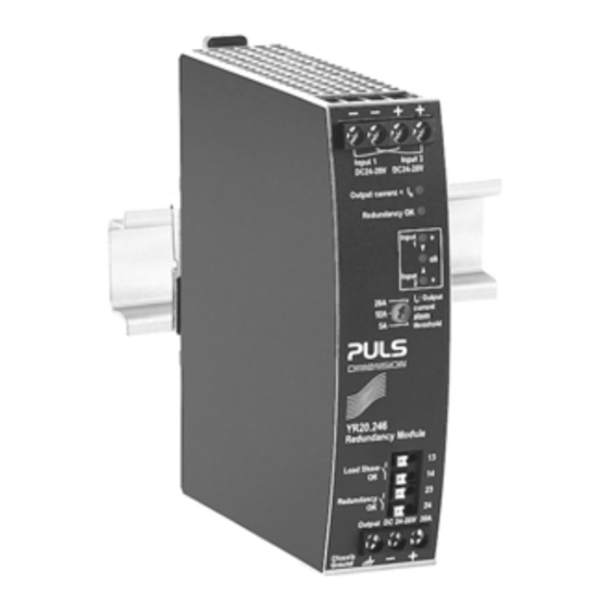
YR20.246 24-28V, 20A, D Y-Series EDUNDANCY ODULE 8. F RONT IDE AND LEMENTS Fig. 8-1 Front side Output terminals (screw terminals) Chassis-Ground terminal Connection of the chassis is optional and not required since the unit fulfils the requirements according to protection class III. C Input terminals for input 1 (screw terminals) D Input terminals for input 2 (screw terminals) Selector for output current warning threshold... -
Page 8: Redundancy Ok" Relay Contact
YR20.246 24-28V, 20A, D Y-Series EDUNDANCY ODULE 9. “R OK” R EDUNDANCY ELAY ONTACT This feature reports the loss of redundancy by opening the relay contact (pin 23 and 24). Contact is closed When no errors are detected Contact is open When: - one or both input voltages are below 22Vdc or above 30Vdc. -
Page 9: Automated Load Sharing
"Load Share OK" contact is closed The active load share feature of the YR20.246 has a similar effect and benefit as the feature “Parallel Mode” (soft output characteristic), which is available on larger PULS power supplies. May 2017 / Rev. 1.3 DS-YR20.246-EN All parameters are typical values specified at 24V, 20A output current, 25°C ambient and... -
Page 10: 12. Emc
YR20.246 24-28V, 20A, D Y-Series EDUNDANCY ODULE 12. EMC The redundancy module is suitable for applications in industrial environment as well as in residential, commercial and light industry environment without any restrictions. EMC Immunity According to generic standards: EN 61000-6-1 and EN 61000-6-2 Electrostatic discharge EN 61000-4-2 Contact discharge... -
Page 11: Environment
YR20.246 24-28V, 20A, D Y-Series EDUNDANCY ODULE 13. E NVIRONMENT Operational temperature -40°C to +70°C (-40°F to 158°F) Storage temperature -40 to +85°C (-40°F to 185°F) for storage and transportation Humidity 5 to 95% r.H. IEC 60068-2-30 Vibration sinusoidal ***) 2-17.8Hz: ±1.6mm;... -
Page 12: Protection Features
YR20.246 24-28V, 20A, D Y-Series EDUNDANCY ODULE 14. P ROTECTION EATURES Output over-current protection not included Reverse input polarity included unit does not start when input voltage is reversed protection Degree of protection IP 20 EN/IEC 60529 Penetration protection > 3.6mm e.g. -
Page 13: Approvals
YR20.246 24-28V, 20A, D Y-Series EDUNDANCY ODULE 17. A PPROVALS EC Declaration of Conformity The CE mark indicates conformance with the - EMC directive and the - ATEX directive (planned). IEC 60950-1 CB Scheme, Information Technology Equipment UL 508 Listed for use as Industrial Control Equipment; U.S.A. -
Page 14: Physical Dimensions And Weight
YR20.246 24-28V, 20A, D Y-Series EDUNDANCY ODULE 19. P HYSICAL IMENSIONS AND EIGHT Width 32mm 1.26’’ Height 124mm 4.88’’ Depth 117mm 4.61’’ The DIN-rail height must be added to the unit depth to calculate the total required installation depth. Weight 310g / 0.69lb DIN-Rail Use 35mm DIN-rails according to EN 60715 or EN 50022 with a height of 7.5 or 15mm. -
Page 15: Accessories
YR20.246 24-28V, 20A, D Y-Series EDUNDANCY ODULE 20. A CCESSORIES 20.1. ZM11.SIDE - S OUNTING RACKET This bracket is used to mount the YR20.246 redundancy module sideways with or without utilizing a DIN-Rail. The two aluminum brackets and the black plastic slider of the unit have to be detached, so that the steel brackets can be mounted. -
Page 16: Application Notes
YR20.246 24-28V, 20A, D Y-Series EDUNDANCY ODULE 21. A PPLICATION OTES 21.1. U SING NPUT NSTEAD OF HANNELS Using only one input instead of both is allowed up to a nominal input current of 12A (at max. +45°C ambient temperature) or 10A (at max. +70°C ambient temperature). The load share feature is disabled in cases one input voltage is not present or the level of the input voltage is below a certain value. -
Page 17: Recommendations For Redundancy
Redundancy Supply Supply Module 1+1 redundancy application with maximum 12A output current. The power supplies are from the PULS DIMENSION series. Output Input Input The redundancy module is placed between the two power supplies. Load The output voltage is set to the same level on both power supplies. -
Page 18: 1+1 Redundancy Up To 10A
YR20.246 24-28V, 20A, D Y-Series EDUNDANCY ODULE 21.5. 1+1 R EDUNDANCY UP TO 1+1 Redundancy up to 10A requires two 10A power supplies and one YR20.246 redundancy module. Fig. 21-5 Wiring diagram, 1+1 Redundancy, 10A output current Load Share Output Output Input Input... -
Page 19: Mounting Orientations
YR20.246 24-28V, 20A, D Y-Series EDUNDANCY ODULE 21.6. M OUNTING RIENTATIONS Mounting orientations other than input terminals on the bottom and output on the top require a reduction in continuous output power or a limitation in the maximum allowed ambient temperature. The amount of reduction influences the lifetime expectancy of the power supply.
Need help?
Do you have a question about the DIMENSION YR40.246 and is the answer not in the manual?
Questions and answers