Table of Contents
Advertisement
Quick Links
Y-Series
1. G
D
ENERAL
ESCRIPTION
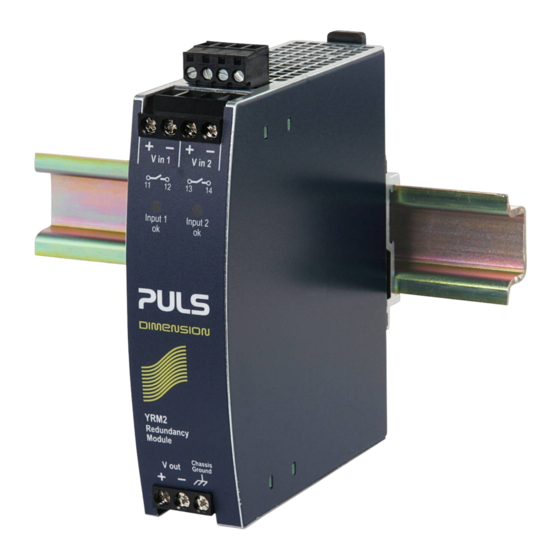
The YRM2.DIODE is a redundancy module, which can
be used for various purposes. The most popular
application is to configure a highly reliable and true
redundant power supply systems. This redundancy
module has a monitoring circuitry included. Two
LEDs and two relay contacts signal when one of the
two DC-input voltages is not in range due to a non-
functioning or disconnected power supply.
Another interesting application is the separation of
sensitive loads from non-sensitive loads. This avoids
the distortion of the power quality for the sensitive
loads which can cause controller failures.
Alongside with the YRM2.DIODE, there exists the
decoupling
module
YR2.DIODE
monitoring circuitry included. This is the perfect fit
when the power supply itself is already equipped
with a DC-OK signal (e.g.: DIMENSION Q-Series).
3. O
N
RDER
UMBERS
YRM2.DIODE
Redundancy
Module
Accessory
ZM1.WALL
ZM11.SIDE
Nov 2006 / Rev. 1.0 DS-YRM2.DIODE-EN
All parameters are specified at 24V, 20A output current, 25°C ambient and after a 5 minutes run-in time unless otherwise noted.
which
has
no
Dual input / single
output
Wall / panel mount
bracket
Side mount bracket
www.pulspower.com Phone +49 89 9278 0
24-60V, 20A, D
UAL
R
M
EDUNDANCY
ODULE
■
Dual input, single output
■
Alarm relay-contacts for each input path
■
Rugged metal housing
■
Width only 32mm
■
Cost effective solution to build redundant systems
■
24-60V Wide-range input
■
20A Continuous output current
■
Easy wiring;
Distribution terminals for negative pole included
■
Large screw terminals
■
3 Year warranty
2. S
-
HORT
FORM
Input voltage
DC 24V
Input voltage range
24-60Vdc
Input current
2x 12.5A
2x 10A
1x 20A
Output current
max. 20A
max. 25A
Input to output
typ. 0.85V
voltage drop
Alarm threshold
typ. 21.5V
Power losses
1 W
18W
Temperature range
-25°C to +70°C
Derating
0.5A/°C
Dimensions
32x124x117mm
4. M
ARKINGS
18WM
LISTED
IND. CONT. EQ.
UL 508, pending
GL
Marine, pending
Germany
YRM2.DIODE
R
M
EDUNDANCY
ODULE
D
ATA
1+1 Redundancy
N+1 Redundancy
Single use
Normal mode
Overload / short-
circuit
At 20A output
current
LED and relay
contact for each
input
At no load
At 20A output
current
Operational
+60 to +70°C
WxHxD
UL 60950-1,
EMC, LVD
pending
1/17
Advertisement
Table of Contents

Related Manuals for Puls Dimension Y Series


Summary of Contents for Puls Dimension Y Series
-
Page 1: General Description
YRM2.DIODE 24-60V, 20A, D Y-Series EDUNDANCY ODULE EDUNDANCY ODULE ■ Dual input, single output ■ Alarm relay-contacts for each input path ■ Rugged metal housing ■ Width only 32mm ■ Cost effective solution to build redundant systems ■ 24-60V Wide-range input ■... -
Page 2: Table Of Contents
YRM2.DIODE 24-60V, 20A, D Y-Series EDUNDANCY ODULE NDEX NDEX General Description ..........1 17. Approvals............10 Short-form Data ..........1 18. Fulfilled Standards..........10 Order Numbers............1 19. Used Substances ..........10 Markings ..............1 20. Physical Dimensions and Weight ..... 11 Input and Output Characteristics .......3 21. -
Page 3: Input And Output Characteristics
YRM2.DIODE 24-60V, 20A, D Y-Series EDUNDANCY ODULE 5. I NPUT AND UTPUT HARACTERISTICS Number of inputs nom. Number of outputs nom. Input voltage nom. DC 24V Input voltage range 22-60Vdc Voltage drop, input to output typ. 0.85V At 2x10A, see Fig. -
Page 4: Power Losses
YRM2.DIODE 24-60V, 20A, D Y-Series EDUNDANCY ODULE 6. P OWER OSSES Power losses typ. 1.0W 10-60Vdc, 0A output current, see Fig. 6-1 4.6W 10-60Vdc, 5A output current, see Fig. 6-1 typ. 8.85W 10-60Vdc, 10A output current, see Fig. 6-1 typ. 18.0W 10-60Vdc, 20A output current, see Fig. -
Page 5: Functional Diagram
YRM2.DIODE 24-60V, 20A, D Y-Series EDUNDANCY ODULE 8. F UNCTIONAL IAGRAM Fig. 8-1 Functional diagram Input 1 Alarm Input Alarm Input 1 Relay Voltage contact Monitor Chassis Ground Input Input 2 Input 2 Voltage Alarm Alarm Monitor Relay contact 9. F RONT IDE AND LEMENTS... -
Page 6: Terminals And Wiring
YRM2.DIODE 24-60V, 20A, D Y-Series EDUNDANCY ODULE 10. T ERMINALS AND IRING Type Screw terminals, Alarm-signal terminals are pluggable IP20 Finger safe construction. Suitable for field- and factory installation. Ferrules allowed, but not required Input and output terminals Alarm-signal terminals Solid wire 0.5-6mm 0.2-1.5mm... -
Page 7: 12. Emc
YRM2.DIODE 24-60V, 20A, D Y-Series EDUNDANCY ODULE 12. EMC The redundancy module is suitable for applications in industrial environment as well as in residential, commercial and light industry environment without any restrictions. CE mark is in conformance with EMC guideline 89/336/EEC and 93/68/EEC and the low-voltage directive (LVD) 73/23/EWG. -
Page 8: Environment
YRM2.DIODE 24-60V, 20A, D Y-Series EDUNDANCY ODULE 13. E NVIRONMENT Operational temperature -25°C to +70°C (-13°F to 158°F) Reduce output power above +60°C Output de-rating 0.5A/°C 60-70°C (140°F to 158°F), see Fig. 13-1 Storage temperature -40°C to +85°C (-40°F to 185°F) Storage and transportation Humidity 5 to 95% r.H. -
Page 9: Protection Features
YRM2.DIODE 24-60V, 20A, D Y-Series EDUNDANCY ODULE 14. P ROTECTION EATURES Output over-current protection not included Degree of protection IP 20 EN/IEC 60529 Penetration protection > 3.5mm E.g. screws, small parts Over-temperature protection Input transient protection Internal input fuse not included Note: In case of a protection event, audible noise may occur. -
Page 10: Approvals
YRM2.DIODE 24-60V, 20A, D Y-Series EDUNDANCY ODULE 17. A PPROVALS UL 508 LISTED E198865 listed for use in U.S.A. 18WM LISTED pending UL 508 Industrial Control Equipment IND. CONT. EQ. UL 60950-1 RECOGNIZED E137006 recognized for the use in U.S.A. (UL 60950- pending 1) and Canada (C22.2 No. -
Page 11: Physical Dimensions And Weight
YRM2.DIODE 24-60V, 20A, D Y-Series EDUNDANCY ODULE 20. P HYSICAL IMENSIONS AND EIGHT Weight 350g / 0.77lb DIN-Rail Use 35mm DIN-rails according to EN 60715 or EN 50022 with a height of 7.5 or 15mm. The DIN-rail height must be added to the depth (117mm) to calculate the total required installation depth. Electronic files with mechanical data can be downloaded at www.pulspower.com Fig. -
Page 12: Accessory
YRM2.DIODE 24-60V, 20A, D Y-Series EDUNDANCY ODULE 22. A CCESSORY ZM1.WALL Wall mounting bracket This bracket is used to mount Dimension units onto a flat surface without utilizing a DIN-Rail. The two aluminum brackets and the black plastic slider of the unit have to be detached, so that the two steel brackets can be mounted. Fig. -
Page 13: Application Notes
YRM2.DIODE 24-60V, 20A, D Y-Series EDUNDANCY ODULE 23. A PPLICATION OTES 23.1. R ECOMMENDATIONS FOR EDUNDANCY Recommendations for the configuration of redundant power systems: • Use separate input fuse for each power supply. • Use Three-phase power supplies to gain functional safety if one phase fails. •... -
Page 14: 1+1 Redundancy Up To 20A
YRM2.DIODE 24-60V, 20A, D Y-Series EDUNDANCY ODULE 23.3. 1+1 R EDUNDANCY UP TO 1+1 Redundancy up to 20A requires two 20A power supplies and two YRM2.DIODE redundancy modules. Fig. 23-2 Wiring diagram, 1+1 Redundancy, 20A output current Failure Monitor IN 1 IN 2 IN 1 IN 2 IN 1... -
Page 15: Battery Back-Up
YRM2.DIODE 24-60V, 20A, D Y-Series EDUNDANCY ODULE 23.5. B ATTERY A battery back-up with 10A requires one 10A power supply and one YRM2.DIODE redundancy module. Please note: Set output voltage of power supply to 26.5Vdc minimum to avoid that the charger current flows to the load instead of charging the battery. -
Page 16: Decoupling Of Buffered Branches
YRM2.DIODE 24-60V, 20A, D Y-Series EDUNDANCY ODULE 23.7. D ECOUPLING OF UFFERED RANCHES Buffer energy supplied from a DC-UPS or buffer module is not wasted in “power branches”. Please note: Set output voltage of the power supply to a level that the buffer unit or DC-UPS will not start unexpected. Take the voltage drop of the YRM2.DIODE into account. -
Page 17: Mounting Orientations
YRM2.DIODE 24-60V, 20A, D Y-Series EDUNDANCY ODULE Mounting Orientations Mounting orientations other than vertical require a reduction in continuous output current or a limitation in the max. allowed ambient temperature. The amount of reduction influences the lifetime expectancy of the power supply. Therefore, two different derating curves for continuous operation can be found below: Curve A1 Recommended output current.
Need help?
Do you have a question about the Dimension Y Series and is the answer not in the manual?
Questions and answers