Puls DIMENSION YR40.245 Manual
12-28v, 40a, single redundancy module
Hide thumbs
Also See for DIMENSION YR40.245:
- Instruction manual (7 pages) ,
- Installation manual (2 pages)
Table of Contents
Advertisement
Quick Links
Y-Series
G
D
ENERAL
ESCRIPTION
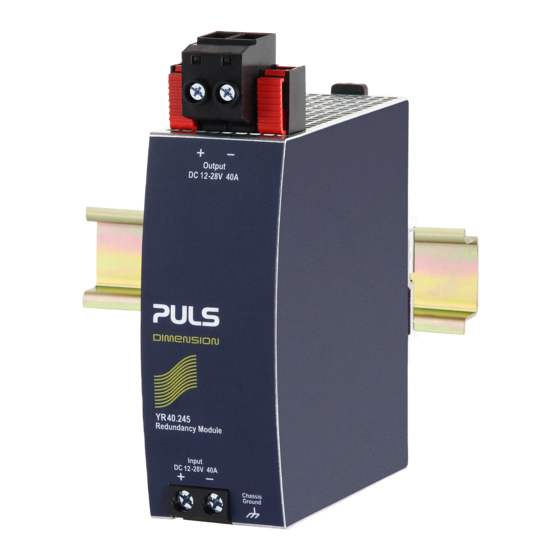
The YR40.245 is a redundancy module, which can be
used to build redundant systems. The module has one
input and one output and can carry nominal currents up
to 40A. The output is equipped with a plug-connector,
which allows replacing the power supply or the
redundancy module while the system is running (hot-
swapping)
The novelty of this redundancy module is the utilization
of mosfets instead of diodes for the decoupling of the
two input channels. This reduces the heat generation
and the voltage drop between input and output. The
redundancy module does not require an additional
auxiliary voltage.
Due to the low power losses, the unit is very slender and
only requires 46mm width on the DIN-rail. Large
connection terminals allow for a safe and fast
installation. The large international approval package
makes this unit suitable for nearly every application.
O
N
RDER
UMBERS
Redundancy
YR40.245
Module
Accessory
ZM2.WALL
ZM12.SIDE
Oct. 2013 / Rev. 1.0 DS-YR40.245-EN
All parameters are specified at 24V, 40A output current, 25°C ambient and after a 5 minutes run-in time unless otherwise noted
12-28V Standard unit
Wall/ panel mount
bracket
Side mount bracket
www.pulspower.com Phone +49 89 9278 0
12-28V, 40A, S
INGLE
M
R
OSFET
EDUNDANCY
Single Input with Single Output
Equipped with Plug-connector for "Hot Swapping"
Suitable for all DIMENSION Power Supplies
Except QT40 Series
Only 150mV Voltage Drop at 40A
Only 6.2W at 40A
160% (65A) Peak Load Capability
Reverse Input Polarity Protection
Full Power Between -40°C and +60°C
Width only 46mm
Rugged Metal Housing
Easy Wiring:
Distribution Terminal for Negative Pole Included
3 Year Warranty
S
-
D
HORT
FORM
Input voltage
DC 12-28V
Input voltage
8.4-36.4Vdc
range
Input current
0-40A
40-65A
Output current
0-40A
40-65A
max. 22A
Input to output
typ. 80mV
voltage drop
typ. 150mV
Power losses
typ. 120mW
typ. 1.8W
typ. 6.2W
Temperature range -40°C to +70°C operational
Derating
1A/°C
*)
Dimensions
46x124x127mm WxHxD
Weight
340g, 0.75lb
*)
Currents at voltages below 6V
**) Plus height for plug connector
M
ARKINGS
IND. CONT. EQ.
UL 508, pending
IECEx
ATEX
II 3G Ex nA IIC T4 Gc
pending
Germany
YR40.245
R
M
EDUNDANCY
ODULE
M
ODULE
ATA
±30%
continuous
for 5 seconds
continuous
for 5 seconds
in overload
short circuit mode
at 20A
at 40A
at no load
at 24V, 20A
at 24V, 40A
+60 to +70°C
UL 60950-1,
Class I Div 2,
pending
pending
EMC, LVD
Marine, pending
*)
or
1/18
Advertisement
Table of Contents

Related Manuals for Puls DIMENSION YR40.245


Summary of Contents for Puls DIMENSION YR40.245
- Page 1 YR40.245 12-28V, 40A, S Y-Series INGLE EDUNDANCY ODULE OSFET EDUNDANCY ODULE Single Input with Single Output Equipped with Plug-connector for “Hot Swapping” Suitable for all DIMENSION Power Supplies Except QT40 Series Only 150mV Voltage Drop at 40A Only 6.2W at 40A 160% (65A) Peak Load Capability Reverse Input Polarity Protection Full Power Between -40°C and +60°C...
-
Page 2: Table Of Contents
YR40.245 12-28V, 40A, S Y-Series INGLE EDUNDANCY ODULE NDEX Page Page Intended Use ............3 14. Dielectric Strength..........12 Installation Requirements........3 15. Approvals ............13 Input and Output Characteristics .......4 16. Fulfilled Standards..........13 Power Losses............5 17. Physical Dimensions and Weight ..... 14 Lifetime Expectancy and MTBF......6 18. -
Page 3: Intended Use
Increase the side clearance to 15mm in case the adjacent device is a heat source (e.g. another power supply). See chapter 19.3 for other allowed clearances when used with the PULS DIMENSION series in a 1+1 redundant configuration. -
Page 4: Input And Output Characteristics
YR40.245 12-28V, 40A, S Y-Series INGLE EDUNDANCY ODULE 3. I NPUT AND UTPUT HARACTERISTICS Number of inputs Number of outputs Input voltage nom. DC 12-28V ±30% The input circuitry must meet the SELV requirements stipulated by IEC/EN/UL 60950-1. Input voltage range 8.4-36.4Vdc Voltage drop, input to output typ. -
Page 5: Power Losses
YR40.245 12-28V, 40A, S Y-Series INGLE EDUNDANCY ODULE 4. P OWER OSSES DC 12V DC 24V Power losses typ. 1.7W 1.8W at 20A 6.1W 6.2W typ. at 40A Standby power losses typ. 0.06W 0.12W at no output current Fig. 4-1 Power losses when both inputs draw equal current Power Losses, typ. -
Page 6: Lifetime Expectancy And Mtbf
YR40.245 12-28V, 40A, S Y-Series INGLE EDUNDANCY ODULE 5. L MTBF IFETIME XPECTANCY AND Load conditions Output: 20A Output: 40A Lifetime expectancy 557 000h 134 000h at 24V and 40°C 1 576 000h 378 000h at 24V and 25°C MTBF SN 29500, IEC 61709 13 290 000h 6 357 000h... -
Page 7: Terminals And Wiring
YR40.245 12-28V, 40A, S Y-Series INGLE EDUNDANCY ODULE 6. T ERMINALS AND IRING Input Output Type Screw termination Pluggable screw termination IP20 Finger safe construction. IP20 Finger safe construction. Suitable for field installation. Suitable for field installation. Solid wire 0.5-16mm 0.2-16mm Stranded wire 0.5-10mm... -
Page 8: Replacing Units While The System Is Running
YR40.245 12-28V, 40A, S Y-Series INGLE EDUNDANCY ODULE 7. R EPLACING NITS WHILE THE YSTEM IS UNNING Fig. 7-1 Replacing the power supply or redundancy module while the system is running Load Power Supply Power Supply Output Output YR40.245 YR40.245 Redundancy Redundancy Module... -
Page 9: Functional Diagram
YR40.245 12-28V, 40A, S Y-Series INGLE EDUNDANCY ODULE 8. F UNCTIONAL IAGRAM Fig. 8-1 Functional diagram control Input Output Chassis Ground 9. F RONT IDE AND LEMENTS Fig. 9-1 Front side Output Terminals (pluggable screw terminals) Chassis Ground Terminals To be connected on the top side of the housing with a ring-type terminal (ring cable lug) which is suitable for a M4 screw. -
Page 10: 10. Emc
YR40.245 12-28V, 40A, S Y-Series INGLE EDUNDANCY ODULE 10. EMC The redundancy module is suitable for applications in industrial environment as well as in residential, commercial and light industry environment without any restrictions. A detailed EMC report is available on request. EMC Immunity According generic standards: EN 61000-6-1 and EN 61000-6-2 Electrostatic discharge... -
Page 11: Environment
YR40.245 12-28V, 40A, S Y-Series INGLE EDUNDANCY ODULE 11. E NVIRONMENT Operational temperature -40°C to +70°C (-40°F to 158°F) Storage temperature -40 to +85°C (-40°F to 185°F) for storage and transportation Output de-rating 1A / °C 60-70°C (140°F to 158°F) Humidity 5 to 95% r.H. -
Page 12: Protection Features
YR40.245 12-28V, 40A, S Y-Series INGLE EDUNDANCY ODULE 12. P ROTECTION EATURES Output over-current protection not included Reverse input polarity included unit does not start when input voltage is reversed protection Degree of protection IP 20 EN/IEC 60529 Penetration protection >... -
Page 13: Approvals
YR40.245 12-28V, 40A, S Y-Series INGLE EDUNDANCY ODULE 15. A PPROVALS EC Declaration of Conformity The CE mark indicates conformance with the - EMC directive 2004/108/EC, - Low-voltage directive (LVD) 2006/95/EC and - RoHS directive 2011/65/EU. The CE mark indicates conformance with the - ATEX directive 94/9/EC (Equipment and protection systems intended for use in potentially explosive atmospheres) IEC 60950-1, pending... -
Page 14: Physical Dimensions And Weight
YR40.245 12-28V, 40A, S Y-Series INGLE EDUNDANCY ODULE 17. P HYSICAL IMENSIONS AND EIGHT Weight 340g / 0.75lb DIN-Rail Use 35mm DIN-rails according to EN 60715 or EN 50022 with a height of 7.5 or 15mm. The DIN-rail height must be added to the unit depth (127mm) to calculate the total required installation depth. -
Page 15: Accessories
YR40.245 12-28V, 40A, S Y-Series INGLE EDUNDANCY ODULE 18. A CCESSORIES ZM2.WALL Wall mounting bracket This standard bracket is used to mount the YR40.245 redundancy module onto a flat surface without utilizing a DIN- Rail. Fig. 18-1 ZM2.WALL Wall mounting bracket Fig. -
Page 16: Application Notes
The clearance between the power supplies and the redundancy module can be reduced to zero under the following conditions: max. 1+1 redundancy application with maximum Load 40A output current. The power supplies are from the PULS DIMENSION series. The redundancy module is placed between Output Output the two power supplies or at least on one... -
Page 17: 1+1 Redundancy Up To 40A
YR40.245 12-28V, 40A, S Y-Series INGLE EDUNDANCY ODULE 19.4. 1+1 R EDUNDANCY UP TO 1+1 Redundancy up to 40A requires two 40A power supplies and two YR40.245 redundancy modules. Fig. 19-1 Wiring diagram, 1+1 Redundancy, 40A output current Failure Monitor Load Output Output... -
Page 18: Mounting Orientations
YR40.245 12-28V, 40A, S Y-Series INGLE EDUNDANCY ODULE 19.6. M OUNTING RIENTATIONS Mounting orientations other than input terminals on the bottom and output on the top require a reduction in continuous output power or a limitation in the maximum allowed ambient temperature. The amount of reduction influences the lifetime expectancy of the power supply.
Need help?
Do you have a question about the DIMENSION YR40.245 and is the answer not in the manual?
Questions and answers