Table of Contents
Advertisement
Quick Links
Advertisement
Table of Contents

Related Manuals for Motorola MVME760


Summary of Contents for Motorola MVME760
- Page 1 MVME760 Transition Module User’s Manual VME760A/UM1...
- Page 2 Motorola, Inc. assumes no liability resulting from any omissions in this document, or from the use of the information obtained therein. Motorola reserves the right to revise this document and to make changes from time to time in the content hereof without obligation of Motorola to notify any person of such revision or changes.
- Page 3 MVME760 Transition Module. The MVME760 module is used as the interface between host VMEmodules and various peripheral devices. A ribbon cable is used to connect the MVME760 Transition Module to the host VMEmodule.
- Page 4 Motorola symbol are registered trademarks of Motorola, Inc. AIX™ is a trademarks of IBM. PowerPC™ is a trademark of IBM, and is used by Motorola with permission. All other products mentioned in this document are trademarks or registered trademarks of their respective holders.
- Page 5 Motorola, Inc. assumes no liability for the customer's failure to comply with these requirements. The safety precautions listed below represent warnings of certain dangers of which Motorola is aware. You, as the user of the product, should follow these warnings and all other safety precautions necessary for the safe operation of the equipment in your operating environment.
- Page 6 This equipment generates, uses, and can radiate electro- magnetic energy. It may cause or be susceptible to electro- magnetic interference (EMI) if not installed and used in a WARNING cabinet with adequate EMI protection.
-
Page 7: Table Of Contents
Contents CHAPTER 1 General Information Introduction ........................1-1 Features of the MVME760 Module ................1-1 Specifications ........................1-2 Cooling Requirements ....................1-2 FCC Compliance ......................1-3 General Description ....................... 1-3 CHAPTER 2 Hardware Preparation and Installation Introduction ........................2-1 Unpacking Instruction .................... - Page 8 INDEX Index ........................IN-1 viii...
- Page 9 Figure 2-2. MVME760 Header Locations............2-3 Figure 2-3. MVME760 Cable Connections ............2-6 Figure 3-1. MVME760 Transition Module Block Diagram ......3-2 Figure 3-2. COM1 and COM2 Configurations ..........3-4 Figure 3-3. Ports 3/4 in EIA-232 DCE Configuration ........3-6 Figure 3-4.
- Page 11 Table 3-3. 10BaseT Connector Pin Assignments ..........3-15 Table 3-4. Parallel I/O Connector Signals (MVME760)........ 3-15 Table 3-5. COM1 and COM2 Interconnect Signals (MVME760) ....3-16 Table 3-6. Pin Assignments for Serial Port 3 Connectors ......3-18 Table 3-7. Serial Port 4 Interconnections ............3-19...
-
Page 13: Introduction
This manual provides general information, hardware preparation, installation instructions, and support information for the MVME760 Transition Module. The MVME760 module is used as the interface between host VMEmodules and various peripheral devices. A 64-pin ribbon cable (P/N 30-W2514B02, 17” length) connects the MVME760 Transition Module to the host VMEmodule. -
Page 14: Specifications
Specifications Specifications The MVME760 module specifications are shown in Table 1-1. Table 1-1. MVME760 Specifications Characteristics Specifications Power Requirements + 5Vdc, 1A maximum (500 mA typical) +12Vdc, 100mA (w/o LAN transceiver) -12Vdc, 100mA I/O Port Connectors Serial Two EIA-232 async serial ports... -
Page 15: Fcc Compliance
General Information FCC Compliance The MVME760 module was tested in an FCC-compliant chassis, and meets the requirements for Class A equipment. FCC compliance was achieved under the following conditions: 1. Shielded cables on all external I/O ports. 2. Cable shields connected to earth ground via metal shell connectors bonded to a conductive module front panel. -
Page 16: Table 1-2. Module Type Identification
General Description Table 1-2. Module Type Identification Model Module Part Number Number Type SIM705-001 EIA-232 DCE 01-W3876Bxx SIM705-002 EIA-232 DTE 01-W3877Bxx SIM705-003 EIA-530 DCE 01-W3878Bxx SIM705-004 EIA-530 DTE 01-W3879Bxx... -
Page 17: Introduction
No preparation is necessary if Serial ports 3 and 4 are not used. However, to ensure full functionality of Serial Port 3 and Serial Port 4, the MVME760 Transition Module must be properly configured. Configuration is accomplished through jumper settings and SIM module population options. -
Page 18: Figure 2-1. Mvme760 Connector Locations
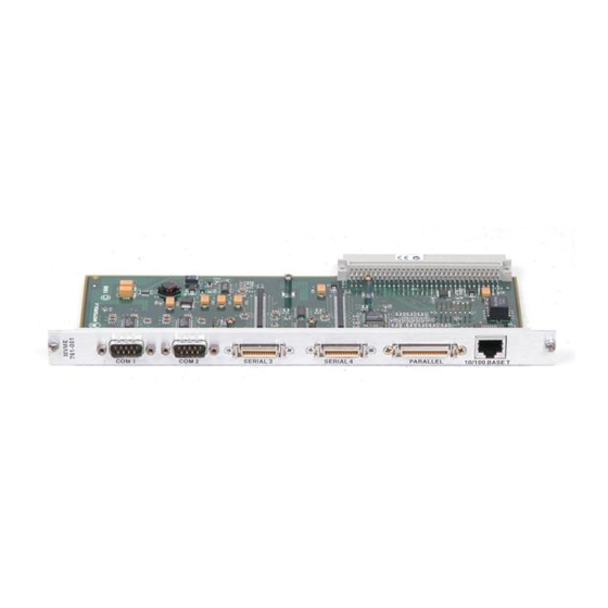
MVME760 Module Preparation BASE BOARD TRANSITION MODULE COM1 COM2 SERIAL PORT 3 64-PIN 50-MIL CABLE PARALLEL PORT 10BASET 1544 9410 Figure 2-1. MVME760 Connector Locations... -
Page 19: Figure 2-2. Mvme760 Header Locations
Hardware Preparation and Installation SERIAL PORT 4 MVME 760-001 MODULE SERIAL PORT 3 (PORT 4) MODULE (PORT 3) 1.1A. POLYSWITCH 1545 9410 Figure 2-2. MVME760 Header Locations... -
Page 20: Configuring Serial Ports 3 And 4
Configuring Serial Ports 3 and 4 Configuring Serial Ports 3 and 4 Headers J9 and J8 are used to configure Serial Port 3 and Serial Port 4, respectively. When the jumper is in position 1-2, the port is configured as a DTE. When the jumper is in position 2-3, the port is configured as a DCE. -
Page 21: Installation Instructions
Hardware Preparation and Installation Installation Instructions The basic procedure for installation of the MVME760 module is as follows: 1. Turn all equipment power OFF and disconnect the power cable from the AC power source. Connecting modules while the power is applied may result in damage to components on the module. -
Page 22: Figure 2-3. Mvme760 Cable Connections
Installation Instructions MVME760 HOST ENCLOSURE BOUNDARY 1548 9412 Figure 2-3. MVME760 Cable Connections... - Page 23 3Support Information Introduction This chapter provides the interconnection signals, parts lists, parts location illustrations, and schematic diagrams for the MVME760 Transition Module. The block diagram for the MVME760 Transition Module is shown in Figure 3-1.
-
Page 24: Chapter 3 Support Information
Support Information 10BaseT PARALLEL COM1 COM2 SERIAL 3 RJ45 DB15 HD36 HD26 26-PIN 3M SERIAL 3 SERIAL 4 26-PIN 3M BUFFERS BUFFERS P2MX FUNCTION EIA-232 EIA-232 64-PIN DIN CONNECTOR 1549 9410 Figure 3-1. MVME760 Transition Module Block Diagram... -
Page 25: Com1 And Com2 Serial Ports
COM1 and COM2 Serial Ports COM1 and COM2 Serial Ports COM1 and COM2 are the two asynchronous serial ports. These two ports are configured as shown in Figure 3-2. -
Page 26: Figure 3-2. Com1 And Com2 Configurations
Support Information TXD1 RTS1_ DTR1_ RXD1 CTS1_ COM1 DSR1_ DCD1_ RI1_ TXD2 RTS2_ DTR2_ RXD2 CTS2_ COM2 DSR2_ DCD2_ RI2_ BASE MVME760 BOARD 1550 9410 Figure 3-2. COM1 and COM2 Configurations... -
Page 27: Serial Ports 3 And 4
Serial Ports 3 and 4 Serial Ports 3 and 4 Serial Ports 3 and 4 can be individually configured as EIA-232-D DCE, EIA-232-D DTE, EIA-530 DCE, or EIA-530 DTE by installing the appropriate Serial Interface Module. Figure 3-3 and Figure 3-4 show the configuration diagrams for Serial Ports 3 and 4 with the EIA-232 DCE and EIA-232 DTE Serial Interface Modules. -
Page 28: Figure 3-3. Ports 3/4 In Eia-232 Dce Configuration
Support Information DB25 Z85230 SCC P2/P2MX (Port 3 only) RTS_ CTS_ DCD_ TXCI TRXC RXCI J9, J8 RTXC TXCO Z8536 CIO DTR_ LLB_ RLB_ DSR_ EIA232-DCE SIM 1554 9411 Figure 3-3. Ports 3/4 in EIA-232 DCE Configuration... -
Page 29: Figure 3-4. Ports 3/4 In Eia-232 Dte Configuration
Serial Ports 3 and 4 DB25 Z85230 SCC P2/P2MX (Port 3 only) RTS_ CTS_ DCD_ TXCO TRXC TXCI J9, J8 RTXC RXCI Z8536 CIO DTR_ LLB_ RLB_ DSR_ EIA232-DTE SIM 1555 9411 Figure 3-4. Ports 3/4 in EIA-232 DTE Configuration... -
Page 30: Figure 3-5. Ports 3/4 In Eia-530 Dce Configuration
Support Information FRONT PANEL DB25 SIM08 Z85230 P2/P2MX (Port 3 only) EIA-530 DCE PORTS 3, 4 PIN 1 TXD_B PIN 14 TXD_A PIN 2 RXD_B PIN 16 RXD_A PIN 3 RTS_B PIN 19 RTS_ RTS_A PIN 4 CTS_B PIN 13 CTS _ CTS_A PIN 5... -
Page 31: Figure 3-6. Ports 3/4 In Eia-530 Dte Configuration
Serial Ports 3 and 4 FRONT PANEL DB25 SIM08 Z85230 P2/P2MX (Port 3 only) EIA-530 DTE PORTS 3, 4 PIN 1 TXD_B PIN 14 TXD_A PIN 2 RXD_B PIN 16 RXD_A PIN 3 RTS_B PIN 19 RTS_ RTS_A PIN 4 CTS_B PIN 13 CTS _... -
Page 32: P2 Connector
64-pin ribbon cable P/N is 30-W2514B02. Table 3-1 shows the interconnect signals. Note Row B is not populated. Power distribution and signaling are accomplished using rows A and C only. Table 3-1. Connector P2 Interconnect Signals (MVME760) Number Signal Mnemonic... -
Page 33: Table 3-1. Connector P2 Interconnect Signals (Mvme760)
P2 Connector Table 3-1. Connector P2 Interconnect Signals (MVME760) (Continued) Number Signal Mnemonic Signal Name and Description SIGNAL GROUND PRSTB_ Refer to the IEEE P1284 D2.00 Standard PRACK_ Refer to the IEEE P1284 D2.00 Standard SIGNAL GROUND PRBSY Refer to the IEEE P1284 D2.00 Standard PRPE Refer to the IEEE P1284 D2.00 Standard... - Page 34 Support Information Table 3-1. Connector P2 Interconnect Signals (MVME760) (Continued) Number Signal Mnemonic Signal Name and Description DTR1 DATA TERMINAL READY (serial port 1) - a signal from the terminal to the modem indicating that the terminal is ready to send or receive data.
- Page 35 P2 Connector Table 3-1. Connector P2 Interconnect Signals (MVME760) (Continued) Number Signal Mnemonic Signal Name and Description DTR2 DATA TERMINAL READY (serial port 2) - a signal from the terminal to the modem indicating that the terminal is ready to send or receive data.
-
Page 36: Ethernet (Aui And 10Baset) Connectors
Support Information Ethernet (AUI and 10BaseT) Connectors The MVME760 provides both AUI and 10BaseT interface via the front panel of the MVME760 transition module. The AUI interface and the 10BaseT interface are provided through a standard 2-row DB15 connector and an RJ45 connector respectively. -
Page 37: Ieee P1284 Parallel I/O Connector
IEEE P1284 Parallel I/O Connector The parallel I/O connector is a standard IEEE P1284-C, 36-pin receptacle on the MVME760 front panel. The functionality of each signal depends on the mode of operation of this bi-directional Parallel Peripheral Interface. Refer to the IEEE P1284 D2.00 Standard for a complete description of each signal function. -
Page 38: Com1 And Com2 Connectors
COM1 and COM2 Connectors Two standard DB9 connectors located on the front panel of the MVME760 transition module provide the interface to the COM1 and COM2 serial ports. The pin assignments for these connectors are shown in Table 3-5. The COM1 and COM2 connector shields are tied to chassis ground. -
Page 39: Serial Port 3 Connectors
Serial Port 3 Connectors Two connectors are provided for Serial Port 3: A 26-pin mini delta ribbon connector located on the front panel of the MVME760 transition module and a 26-pin ribbon-cable (3M-type) header located on the board itself. The pin assignments for these two connectors are shown in Table 3-6. - Page 40 Support Information Pin Assignments for Serial Port 3 Connectors Table 3-6. Front-panel 3m-Type Connector Ribbon Connector Mated DB25 Mated DB26 Pin # Signal Name Pin # Signal Name Pin # Pin # No Connect No Connect TXD3 TXD3 RXD3 RXD3 RTS3 RTS3 CTS3...
-
Page 41: Serial Port 4 Connector
Serial Port 4 Connector Serial Port 4 Connector A 26-pin ribbon-cable (3M-type) header provides the interface to Serial Port 4. Ribbon cable with mating connector can be used to interface to this header. The pin assignments for this connector are shown in the following table. -
Page 42: Serial I/O Data Rate
Parts lists are illustrated in Table 3-8. Parts locations are illustrated in Figure 3-7. Model Parts List Parts Location Drawing MVME760 Table 3-8 Figure 3-7 Table 3-8. MVME760 Module Parts List Reference Motorola Designation Part Number Description 84-W8000F01A Printed wiring board (MVME760) - Page 43 Parts Lists and Locations Table 3-8. MVME760 Module Parts List (Continued) Reference Motorola Designation Part Number Description Capacitor, fixed, 33 µF @15 Vdc 23NW9712A06 C44,47,51 21NW9711A11 Capacitor, fixed, ceramic, 22pF 06NW9650A01 Polyswitch, 1.1A J1, 3 28NW9802H73 Connector, 9-pin plug J2, 7...
- Page 44 Support Information Table 3-8. MVME760 Module Parts List (Continued) Reference Motorola Designation Part Number Description U14, 15 51NW9637C20 I.C., MC74F257AD, 16-pin 64-W4478C01A Front Panel (MVME760-001) 30-W2514B02 17” length, 64-pin ribbon cable 3-22...
-
Page 45: Figure 3-7. Mvme760 Parts Location Drawing
Parts Lists and Locations MVME 760-001 1551 9410 Figure 3-7. MVME760 Parts Location Drawing 3-23... -
Page 46: Schematic Drawings
Support Information Schematic Drawings Schematic drawings for the MVME760 Transition Module are shown on the following pages. 3-24... - Page 47 Index When using this index, keep in mind that a page number indicates only where referenced material begins. It may extend to the page or pages following the page referenced. Numerics 10BaseT Connector Pin Assignments I/O Ports IEEE P1284 Parallel I/O Connector 3-15 3-15 Installation Instructions...
- Page 48 Index Schematic Drawings 3-22, 3-24 Serial I/O Data Rate 3-20 Serial Interface Modules Serial Port 4 Connector 3-19 Serial Ports 3 and 4 Specifications Storage temperature Unpacking Instruction IN-2...
Need help?
Do you have a question about the MVME760 and is the answer not in the manual?
Questions and answers