Advertisement
Quick Links
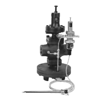
Figure 1 -1. For Steam Service
Globe
Valve
By-Pass
Armstrong
Strainer
Minimum of 10 Inlet
Pipe Diameters from
PRV to First Turn
Armstrong
TVS Trap
This bulletin should be used by experienced personnel as a guide to the installation of the Model OB 2000PT Pressure/
Temperature Regulating Valve. Selection or installation of equipment should always be accompanied by competent
technical assistance. You are encouraged to contact Armstrong International, Inc. or its local sales representative for
additional information.
1. An Armstrong TVS Inverted Bucket Steam Trap is
recommended to drain condensate at the inlet of the
temperature regulator.
2. An Armstrong 100 mesh screen "Y" strainer should be
installed before the pressure/temperature regulator to
reduce the chance of dirt fouling.
3. A pressure gauge is recommended before and after
the pressure/temperature regulator.
4. If standard piping practice permits, a bypass line
around the pressure/temperature regulator is
recommended. The bypass line should run horizontal
to the steam line.
5. The control pipe connects to a ¼" tapping on the side
of the pressure pilot valve. Be certain the control pipe
is pitched away from the pressure/temperature
regulator. Erratic control could result if this is not
done. The pipe should be installed a minimum of 10
outlet pipe diameters downstream of the last
obstruction.
Model OB 2000PT
Pressure/Temperature Regulating Valve
Installation, Operation and Maintenance Instructions
Gate
Valve
2
OB 2000PT
Minimum of 20 Outlet
Pipe Diameters from
PRV to First Turn
Note:
1 Safety Relief Valve to be set at 10 psi higher or 10%
higher than the downstream pressure, whichever is greater.
2 It is suggested that the inlet "Y" type strainer be installed
on it's side to avoid the collection of liquid in the body that
could be carried through the regulator as a damaging slug
under certain conditions.
Installation Instructions
Control Pipe
(Pitch Down)
Minimum of 10 Outlet
Pipe Diameters from
Last Valve or Fitting
Swing Check Valve
(Vacuum Breaker)
6. Install the pressure/temperature regulator with the
main diaphragm housing down. Make sure the flow is
in the direction of the arrow on the body of the valve.
7. A vacuum breaker should be installed after the outlet
of the heater coil and before the steam trap.
Automatic air vents should also be installed at all
points where non-condensibles can collect.
8. Avoid lifting condensate directly after steam traps.
Under light loads the pressure in the steam space is
reduced and often is too low to lift condensate.
Gravity drain to return pump is recommended, or pipe
in a safety drain trap. (See Steam Conservation
Guidelines section in Bulletin 326).
Assembly & Installation
The pressure/temperature regulator will come in two (2)
boxes. One box will contain an integral mount (pressure
pilot mounted on the top of the main valve) main valve and
the second box containing the temperature pilot with
fittings which is not connected to the integral mounted
valve and the capillary system. Please read the instruction
bulletin before assembly and installation.
Bulletin No. AY-731-A
Safety Relief
1
Valve
Thermometer
Armstrong
F&T Trap
Advertisement

Related Manuals for Armstrong OB 2000PT


Summary of Contents for Armstrong OB 2000PT
- Page 1 Armstrong F&T Trap This bulletin should be used by experienced personnel as a guide to the installation of the Model OB 2000PT Pressure/ Temperature Regulating Valve. Selection or installation of equipment should always be accompanied by competent technical assistance. You are encouraged to contact Armstrong International, Inc. or its local sales representative for additional information.
- Page 2 1. Once the valve body is installed, insert bellows 1. Open valve on drip leg to allow inverted bucket follower (10), which was packaged with the steam trap to drain condensate on OB 2000PT capillary system inside the sensor bellows (35) inlet.
- Page 3 (24). 3. Remove four hexagonal bolts (17) from the spring housing (2) and remove adjusting spring (14). 5. Open valve on outlet of OB 2000PT and also on control pipe. 4. Remove top bellows plate (6) and top seal bellows (5).
- Page 4 2. Make sure all sliding parts (main spindle) move freely. OB 2000PT Pilot Valve Assembly Figure 4-1 For Steam Service Adjusting Screw (15) Body (1)
- Page 5 OB 2000PT Pressure/Temperature Regulating Valve Integral Mount Pilot Assembly Figure 5-1 For Steam Service Main Valve Seat (7) Fitting (30A) Gasket (8) Adjusting Screw (27) Lock Nut (28) Pipe D (46) Rivet (43) (pipe configuration Nameplate (42) not exact) Body (1)
-
Page 6: Troubleshooting Guide
External leak. Broken top bellows seal (5). Replace top bellows seal. Kit K-2611 Armstrong-Yoshitake, Inc. , 221 Armstrong Blvd., P.O. Box 408, Three Rivers, MI 49093 - USA Ph: (269) 279-3600 Fax: (269) 273-8656 www.armstrong-intl.com Bulletin No. AY-731-A 1/03 Printed in U.S.A.
Need help?
Do you have a question about the OB 2000PT and is the answer not in the manual?
Questions and answers