Advertisement
I. Internals Maintenance:
- For maintenance of trap internals, see Armstrong IOM-1001.
II. Valves Maintenance:
- Make sure to interrupt steam flow up and down stream in order to isolate the
TVS;
- Using the TVS's handwheels (11), open completely each TVS's valve;
- Unscrew the bonnet bolts (13) and pull the isolation valve assembly (10) out of
valve body;
- TVS-811: Place the special tool A-9542 (sealing ring extractor) into the body of
the valve and turn its top square nut (A) in order to allow the spindle (C) to expand
under the valve washer (5);
- TVS-812 & TVS-813: Place the special tool B-5259 (sealing ring extractor) into
the body of the valve and turn its top square nut (A) in order to allow the spindle
(C) to expand under the valve washer (5);
- Turn the lower nut (B) of the extractor in order to pull the tool out of the valve
body. The disc springs (3), valve sealing rings (4) and lantern bushing (7) will
come out on the end of the tool.
Check to see if all components have been
removed and clean any remaining debris.
- TVS-811: Place valve washer (5) into valve body with Beveled Edge down;
- TVS-812 & TVS-813: Place valve washer (5) into valve body;
- TVS-811: Place Armstrong part B-5249 (isolation valve assembly) into valve
body and lightly tap it to the bottom. Screw evenly the bolts (13) until the bonnet
(10) seats on the valve body;
- TVS-812 & TVS-813: Place Armstrong part B-5250 (isolation valve assembly) into
valve body and lightly tap it to the bottom. Place 2 bonnet disc springs (8) - oval
surfaces facing each other - on each stud (12) and coat the studs (12).
Place the bonnet nuts (14) on the studs (12) and tighten evenly.
I. Wartung Innenteile:
- Armstrong IOM-1001für Wartung der Innenteile des Kondensatableiters verwenden.
II. Wartung der Ventile:
- Absperren der Dampfzufuhr und Kondensatseite um TVS von der Leitung zu trennen;
- Mit den Handrädern (11) beide TVS-Ventile voll öffnen;
- Schrauben am Bügeldeckel (13) lösen und Ventileinheit (10) aus Ventilgehäuse
ziehen;
- TVS-811: Spezialwerkzeug A-9542 (Auszieher für Dichtungsring) in Ventilgehäuse
einführen und oberen Vierkant (A) drehen, sodaß sich Spindel (C) unterhalb der
Ventildichtung (5) ausdehnen kann;
- TVS-812 & TVS-813: Spezialwerkzeug B-5259 (Auszieher für Dichtungsring) in
Ventilgehäuse einführen und oberen Vierkant (A) drehen, sodaß sich Spindel (C)
unterhalb der Ventildichtung (5) ausdehnen kann;
- Untere Sechskantmutter (B) des Ausziehers festschrauben und Werkzeug aus dem
Ventilgehäuse ziehen; Federscheibe (3) Ventil-Dichtungsringe (4) und die Laterne (7)
werden
mit
dem
Werkzeug
herausgezogen.
Sicherstellen,
daß
alle T eile
wurden und Bohrung von evtl. zurückgebliebenen Bruchstücken reinigen;
- TVS-811:
Ventildichtung
(5)
mit
abgeschrägter
Kante
unten
in
Ventilgehäuse
einsetzen.
- TVS-812 & TVS-813: Ventildichtung (5) in Ventilgehäuse einsetzen.
- TVS-811: Armstrong Ersatzteil B-5249 (Ventileinheit) in Ventilgehäuse einsetzen
und leicht gegen Boden festsklopfen. Schrauben (13) gleichmäßig festziehen bis der
Bügel (10) am Ventilgehäuse aufsitzt;
- TVS-812 & TVS-813: Armstrong Ersatzteil B-5250 (Ventileinheit) in Ventilgehäuse
einsetzen
und leicht gegen Boden festsklopfen; 2 Federscheiben (8) für Bügel -
ovale
Oberflächen
gegenüber
-
auf
jeden
Bolzen
(12)
stecken
und
Bolzen
einstreichen.
Muttern
(14)
auf
Bolzen
(12)
setzen
und
gleichmäßig
festziehen.
I. Entretien des pièces internes:
- Pour l'entretien des pièces internes, voir le document Armstrong IOM-1001.
II. Entretien des vannes :
- Couper la
vapeur en amont et en aval afin d'isoler le TVS;
- En utilisant les volants du TVS (11), ouvrir complètement chacune des vannes;
- Dévisser les boulons du bonnet (13) et retirer l'assemblage (10) du corps de la
vanne;
- TVS-811: Placer l'outil spécial A-9542 (extracteur) dans le corps de la vanne et
visser le boulon carré (A) pour permettre à la tige (C) de s'élargir sous la rondelle (5);
- TVS-812 & TVS-813: Placer l'outil spécial B-5259 (extracteur) dans le corps de la
vanne et visser le boulon carré (A) pour permettre à la tige (C) de s'élargir sous la
rondelle (5);
- Serrer l'écrou inférieur (B) de l'extracteur et retirer l'outil du corps de la vanne. Les
ressorts circulaires (3), les bagues d'étanchéité (4) et la lanterne (7) vont sortir de la
vanne, au bout de l'outil. Vérifier que tous les composants ont été retirés et bien
nettoyer le moindre débris;
- TVS-811: Placer la rondelle (5) dans le corps de la vanne avec
le côté chanfreiné
vers le bas;
- TVS-812 & TVS-813: Placer la rondelle (5) dans le corps de la vanne;
- TVS-811: Placer la pièce Armstrong N° B-5249 (empilage de joints) dans le corps
de la vanne et le faire glisser au fond en tapant légèrement. Visser les boulons (13)
de manière équilibrée jusqu'à ce que le bonnet (10) se pose sur le corps de la vanne;
- TVS-812 & TVS-813: Placer la pièce Armstrong N° B-5250 (empilage de joints)
dans le corps de la vanne et le faire glisser au fond en tapant légèrement. Placer les
2 ressorts circulaires du bonnet (8) - avec les faces ovales l'une contre l'autre - sur
chaque goujon (12) et enduire les goujons de graisse (12). Placer les
écrous du bonnet (14) sur les goujons (12) et serrer de manière équilibrée.
Armstrong International S.A., Parc Industriel des Hauts-Sarts, 4040 Herstal - Belgium
IOM-1017-B
10/2005
I. Mantenimiento de las piezas internas:
- Para el mantenimiento de piezas internas en purgadores, consulte Armstrong IOM-
1001.
II. Mantenimiento de las válvulas:
- Asegúrese de interrumpir el flujo de vapor ascendente y descendente para aislar el
TVS;
- Utilice los volantes del TVS (11) para abrir por completo cada válvula;
- Afloje los pernos del bonete (13) y retire del cuerpo el conjunto de válvulas de
aislamiento (10);
- TVS-811: Coloque la herramienta especial A-9542 (extractor del anillo de cierre)
dentro del cuerpo de la válvula y gire la tuerca cuadrada superior (A) de manera que
el eje (C) se expanda debajo de la arandela de la válvula (5);
- TVS-812 y TVS-813: Coloque la herramienta especial B-5253 (extractor del anillo de
cierre) dentro del cuerpo de la válvula y gire la tuerca cuadrada superior (A) de manera
que el eje (C) se expanda debajo de la arandela de la válvula (5);
- Ajuste la tuerca inferior (B) del extractor y quite la herramienta del cuerpo de la
válvula. Los resortes de disco (3), los anillos de cierre de la válvula (4) y el buje linterna
(7) saldrán en la parte inferior de la herramienta. Verifique que todos los componentes
fueron retirados y limpie los restos que puedan quedar.
- TVS-811: Coloque la arandela (5) dentro del cuerpo de la válvula con el borde
biselado hacia abajo;
- TVS-812 y TVS-813: Coloque la arandela (5) dentro del cuerpo de la válvula;
- TVS-811: Coloque la pieza Armstrong B-5249 (conjunto de válvulas de aislamiento)
dentro
del
cuerpo
de
la
válvula
y
golpéela
ligeramente
uniformemente los pernos (13) hasta que el bonete (10) se apoye en el cuerpo de la
válvula;
- TVS-812 y TVS-813: Coloque la pieza Armstrong B-5250 (conjunto de válvulas de
aislamiento) dentro del cuerpo de la válvula y golpéela ligeramente hacia el
fondo.
Coloque
dos
resortes
de
disco
(8)
-
con
las
enfrentadas
-
en
cada
perno
(12)
y
cubra
los
pernos
tuercas del bonete (14) en los pernos (12) y ajuste uniformemente.
I. Onderhoud aan binnenwerk:
- Voor onderhoud en reparatie aan condenspot, zie blad IOM-1001.
II. Afsluiter onderhoud en reparatie:
- Verzeker u ervan dat zowel de toe- als de afvoer naar de TVS afgesloten zijn;
- Draai d.m.v. de handwielen (11) beide afsluiters geheel open;
- Demonteer de drukstukbouten
(13) en trek het afsluiter binnenwerk (10) geheel
uit het huis;
- TVS-811: Plaats het speciale gereedschap A-9542 in het afsluiterhuis en draai
de topbout (A) , waardoor de spindel (C) uitzet onder de onderste afdichtring (5);
- TVS-812
&
TVS-813:
Plaats
het
speciale
gereedschap
afsluiterhuis en draai de topbout (A) , waardoor de spindel (C) uitzet onder de
onderste afdichtring (5);
- Draai de moer (B) en trek het gereedschap uit het huis. De veerringen (3), de
afdichtringen
(4)
en
de
lantaarnring
(7)
komen
met
Controleer of alle onderdelen verwijderd zijn en reinig de binnenkant van het huis.
entfernt
- TVS-811: Plaats de ring (5) met de schuine kant naar beneden in het huis;
- TVS-812 & TVS-813: Plaats de ring (5) in het huis;
- TVS-811: Plaats het bovendeel (B-5249 voorzien van nieuwe ringen) in het huis
en druk dit stevig, maar voorzichtig door tot op de bodem. Draai de bouten (13)
gelijkmatig aan, totdat het drukstuk (10) op het afsluiterhuis
- TVS-812 & TVS-813: Plaats het bovendeel (B-5250 voorzien van nieuwe ringen)
in het huis en druk dit stevig, maar voorzichtig door tot op de bodem. Plaats 2
veerringen (8) met de ovale vlakken naar elkaar toe, op elk draadeind (12) en
smeer de draadeinden (12). Draai de bouten (14) gelijkmatig aan.
(12)
I. Manutenzione degli organi interni:
- Per la manutenzione degli organi interni vedere istruzioni
II. Manutenzione delle valvole:
- Interrompere il flusso vapore ed isolare il gruppo TVS;
- Aprire completamente le 2 valvole, agendo sui volantini (11);
- Svitare i bulloni (13) del bonnet ed estrarre gli interni (10) fuori dal corpo valvole;
- TVS-811: Posizionare nel corpo valvola l'utensile speciale A-9542 (Estrattore
anelli
di
tenuta)
e
girando
(A)
far
espandere
lo
spinotto
rondella
(5);
- TVS-812 & TVS-813: Posizionare nel corpo valvola l'estrattore anelli di tenuta
B-5259 e girando (A) far espandere lo spinotto (C) al di sotto della rondella (5);
- Stringere il dado (B) e tirar fuori l'estrattore dal corpo valvola. Le molle a tazza
(3), gli anelli di tenuta (4) e la lanterna (7) verranno così estratti. Controllare se
tutti i componenti sono stati rimossi e procedere con le normali operazioni di
pulizia delle parti interessate;
- TVS-811: Riposizionare nel corpo valvola la rondella (5), con la parte smussata
in basso;
- TVS-812 & TVS-813: Riposizionare nel corpo valvola la rondella (5);
- TVS-811:
Riposizionare
l'assieme
B-5249
nel
corpo
delicatamente sino al fondo. Avvitare uniformemente i bulloni (13) sino a che il
bonnet (10) sia correttamente posizionato sul corpo valvola;
- TVS-812
&
TVS-813:
Riposizionare
l'assieme
B-5250
avvitarlo delicatamente sino al fondo. Posizionare le 2 molle a tazza (8) su ogni
tirante (12).
Posizionare i dadi (14) sui tiranti
(12) e stringerli uniformemente.
Ph: +32.4.240.90.90
Fax: +32.4.248.13.61
www.armstrong.be
hacia
el
fondo.
Ajuste
Scaricatori di Condensa a Secchiello Rovesciato
superficies
ovales
(12).
Coloque
las
Ces instructions devraient être utilisées par du personnel expérimenté !
¡Estas instrucciones deben ser utilizadas por personal experimentado !
A-5259
in
het
PRODUCT DESCRIPTION - PRODUKTBESCHREIBUNG - DESCRIPTION DU PRODUIT
DESCRIPCION DEL PRODUCTO - PRODUKT OMSCHRIJVING - DESCRIZIONE DEL PRODOTTO
het
gereedschap
mee;
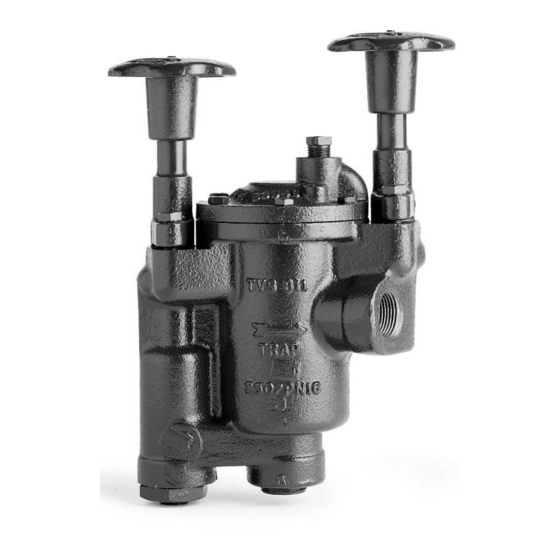
Model shown on the picture: TVS-811 - Die Abbildung zeigt das Modell TVS-811 - Photo: modèle TVS-811
Armstrong Cast Iron Trap Valve Station
Horizontal Connection
zit;
Optional: Internal Strainer
Armstrong Multifunktionseinheit aus Grauguß
Waagerechter Einbau
Option: Eingebauter Schmutzfänger
Station de Purge Armstrong en Fonte
Raccordement Horizontal
Armstrong IOM-1001.
En Option : Filtre Intégré
Estación de Válvulas de Purgadores Armstrong en Fundición
Conexión Horizontal
Opcional: Filtro Interno
(C)
al
di
sotto
della
Armstrong Gietijzeren Trap Valve Station.
Horizontale Aansluiting
Optie: Ingebouwd Filter
Gruppo di Drenaggio Compatto "Scaricatore e Valvole Integrate" - In Ghisa
Connessioni Orizzontali
Accessori Opzionali: Filtro Integrato
valvola
ed
avvitarlo
For detailed material specifications, options, approximate dimensions and weights, see Armstrong literature or consult your local Representative.
nel
corpo
valvola
ed
Für detaillierte
Werkstoffangaben, Zubehör, Abmessungen und Gewichte, sehen Sie die Armstrong Datenblätter oder fragen Sie Ihre Armstrong-Vertretung.
Pour toute spécification détaillée des matières, options, dimensions et poids, veuillez vous référer à la littérature Armstrong ou prendre contact avec votre
Représentant local.
Para
especificaciones
Representante local.
Voor
gedetailleerde
materiaal
Vertegenwoordiger.
Per la specifica dettagliata dei materiali, accessori opzionali, dimensioni e pesi approssimativi, vedere la documentazione appropriata o contattare il
Printed in Belgium
Distributore locale.
Series TVS-800
Inverted Bucket Steam Traps
Glockenkondensatableiter
Purgeurs à Flotteur Inversé Ouvert
Purgadores de Vapor de Cubeta Invertida
Omgekeerde Emmer Condenspot
These instructions should be used by experienced personnel !
Diese Gebrauchsanweisung ist durch Fachpersonal zu benutzen !
Onderhoud uitsluitend uit te voeren door ervaren personeel !
Queste istruzioni devono essere utilizzate da personale esperto !
Modelo mostrado en la fotografía: TVS-811 - Model op foto: TVS-811 - Modello in figura: TVS-811
de
materiales
detalladas,
opciones,
dimensiones
aproximadas
specificaties,
afmetingen
en
gewichten,
zie
de
Armstrong
y
pesos,
ver
catálogos
Armstrong
o
consultar
con
su
documentatie
of
neem
contact
op
met
uw
plaatselijke
Advertisement
Table of Contents

Related Manuals for Armstrong TVS-800 Series


Summary of Contents for Armstrong TVS-800 Series
- Page 1 (12) e stringerli uniformemente. Pour toute spécification détaillée des matières, options, dimensions et poids, veuillez vous référer à la littérature Armstrong ou prendre contact avec votre 2 ressorts circulaires du bonnet (8) - avec les faces ovales l'une contre l'autre - sur Représentant local.
- Page 2 Für detaillierte Informationen über Installation, Inbetriebnahme und Außerbetriebnahme sehen Sie die Armstrong Datenblätter oder fragen Sie Ihre Armstrong-Vertretung. Pour plus de détails à propos des procédures de démarrage et d'arrêt, ainsi que pour l'installation, veuillez vous référer à la littérature Armstrong ou prendre contact avec votre Représentant local.
Need help?
Do you have a question about the TVS-800 Series and is the answer not in the manual?
Questions and answers