Table of Contents
Advertisement
Advertisement
Table of Contents
Troubleshooting

Related Manuals for SCIEX NanoSpray


Summary of Contents for SCIEX NanoSpray
- Page 1 ® NanoSpray Ion Source Operator Guide RUO-IDV-05-0811-F May 2018...
- Page 2 SCIEX warranties are limited to those express warranties provided at the time of sale or license of its products and are SCIEX s sole and exclusive representations, warranties, and obligations.
-
Page 3: Table Of Contents
® Remove the NanoSpray III Head............................26 Prepare the Sprayer Fitting..............................28 Insert the Emitter Tip...............................30 Install the NanoSpray III Head on the Bracket.........................31 Connect the Sample Line..............................32 Adjust the Illuminator and Camera..........................34 Adjust and Focus the Camera............................34 Adjust the Illuminator..............................36 ®... - Page 4 Change to a Different Ion Source (OptiFlow Interface Components)..............49 ® Change to the NanoSpray Ion Source (OptiFlow Interface Components)................................49 ® Change to a Different Ion Source (NanoSpray Interface Components)..............49 ® ® Change to the NanoSpray Ion Source (NanoSpray Interface Components)................................50 Change the Interface Components...........................50...
- Page 5 Contents C Connecting the Syringe Using PEEK-lined Fused Silica Tubing............83 D Source Parameters and Voltages......................87 E Glossary of Symbols..........................88 ® Operator Guide NanoSpray Ion Source RUO-IDV-05-0811-F 5 / 92...
-
Page 6: Operational Precautions And Limitations
® WARNING! Hot Surface Hazard. Let the NanoSpray ion source cool for at least 60 minutes before starting any maintenance procedures. Surfaces of the ion source become hot during operation. -
Page 7: Chemical Precautions
• Determine which chemicals have been used in the system prior to service and regular maintenance. Refer to the Safety Data Sheets for the health and safety precautions that must be followed with chemicals. SCIEX Safety Data Sheets can be found at sciex.com/tech-regulatory. -
Page 8: System Safe Fluids
The following fluids can safely be used with the system. CAUTION: Potential System Damage. Do not use any other fluid until confirmation is received from SCIEX that it does not present a hazard. This is not an exhaustive list. • Organic Solvents •... -
Page 9: Laboratory Conditions
Over time, the temperature must remain within a range of 4 °C (7.2 °F), with the rate of the change in temperature not exceeding 2°C (3.6°F) per hour. Ambient temperature fluctuations exceeding the limits might result in mass shifts in spectra. • Relative humidity from 20% to 80%, non-condensing ® Operator Guide NanoSpray Ion Source RUO-IDV-05-0811-F 9 / 92... -
Page 10: Equipment Use And Modification
WARNING! Personal Injury Hazard. Use SCIEX-recommended parts only. Use of parts not recommended by SCIEX or use of parts for any purpose other than their intended purpose can put the user at risk of harm or negatively impact system performance. -
Page 11: Related Documentation
SCIEX website at sciex.com. Laser Safety Information ® This section contains safety information for the laser used in the illuminator for the NanoSpray III ion source. Laser Classification WARNING! Laser Hazard. Do not view the laser output with an optical instrument. -
Page 12: Scheduled Maintenance
Avoid eye or skin exposure to direct or scattered radiation. Complies with 21 CFR 1040.10 and External. On the top cover. 1040.11 except for deviations pursuant to Laser Notice No. 50, dated June 24, 2007 ® NanoSpray Ion Source Operator Guide 12 / 92 RUO-IDV-05-0811-F... - Page 13 Laser Radiation: Avoid direct eye exposure. External. On the top cover. Class 3R laser product. Max power: 5 mW; Wavelength: 650 nm; IEC 60825-1 ® Operator Guide NanoSpray Ion Source RUO-IDV-05-0811-F 13 / 92...
-
Page 14: Ion Source Overview
® The NanoSpray ion source is ideally suited for the analysis of polar, thermally labile compounds by mass spectrometry. It is an atmospheric pressure ionization (API) source that provides high ionization efficiency for the transfer of analytes into gas phase ions. -
Page 15: Ion Source Components
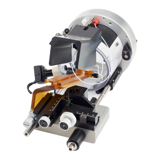
Description Cover. Laser warning labels (not shown) are located on the top of this cover. Ion source interface Release pin Release latch Camera. Refer to Adjust and Focus the Camera. ® Operator Guide NanoSpray Ion Source RUO-IDV-05-0811-F 15 / 92... -
Page 16: Camera And Illuminator
Item Description X-Y-Z positioning unit Positioning rails Sleeve X-Y-Z adjustment knobs (micrometers) ® Bracket. The ion source head is installed on the bracket. Refer to NanoSpray III Head Assembly and Installation. Protective end cap Illuminator. Refer to Adjust the Illuminator. - Page 17 Ion Source Components Figure 3-2 Camera and Illuminator Item Description Illuminator Camera ® Operator Guide NanoSpray Ion Source RUO-IDV-05-0811-F 17 / 92...
-
Page 18: Ion Source Head
III head. The ion source head holds the union that connects the fused silica or nano LC column to the emitter tip. The mass spectrometer supplies high-voltage power to the ion source head and the union holder. Figure 3-3 Ion Source and NanoSpray III Head Item Description ®... -
Page 19: Positioning Rails
Moving the X-Y-Z positioning unit away from the ion source interface disconnects the high-voltage supply from the ion source head and allows the ion source head to be removed. The ® Operator Guide NanoSpray Ion Source RUO-IDV-05-0811-F 19 / 92... -
Page 20: Nanospray ® Interface Components
X-Y-Z positioning unit is pushed completely into its operating position. ® NanoSpray Interface Components ® The ion source housing connects to the NanoSpray interface components. Refer to Figure 3-5. The interface components consist of the orifice plate and the curtain plate. ®... - Page 21 Ion Source Components ® Note: The OptiFlow interface components are applicable only to the TripleTOF 6600 system. Figure 3-6 OptiFlow Interface Components Item Description Nano cell heater assembly Nano cell curtain plate ® Operator Guide NanoSpray Ion Source RUO-IDV-05-0811-F 21 / 92...
-
Page 22: Requirements
We recommend pre-made high purity solvents such as those from Burdick-Jackson (that is, HPLC-grade water with 0.1% formic acid and acetonitrile with 0.1% formic acid). These solvents can be ordered from VWR (US PN BJLC452-2.5 - 0.1% Formic Acid#Water, US PN BJLC441-2.5 - 0.1% Formic Acid#Aceton). ® NanoSpray Ion Source Operator Guide 22 / 92... -
Page 23: Nanospray ® Iii Head Assembly And Installation
NanoSpray III Head Assembly and Installation ® This section describes how to assemble and install the NanoSpray III head. It includes procedures for preparing the head and emitter tips. Tip! For additional training materials, go to SCIEXUniversity. Figure 4-1 NanoSpray III Head Components... -
Page 24: Assemble The Nanospray Iii Head
— ® Assemble the NanoSpray III Head ® The following types of emitter tips can be used with the NanoSpray III head: • Pre-cut New Objective tips • Uncut New Objective tips • Pre-packed column tips Note: Emitter tips are also referred to as fused silica capillaries or needles. - Page 25 ® NanoSpray III Head Assembly and Installation ® Figure 4-2 Parts for the NanoSpray III Head Item Description Part Number Sprayer fitting (PEEK nut and ferrule) 5031772 Both Green FEP sleeve (1.58 mm outside diameter 1006547 Consumables [o.d.], 0.38 mm inside diameter [i.d.])
-
Page 26: Remove The Nanospray Iii Head
Follow all electrical safe work practices. ® WARNING! Electrical Shock Hazard. Never operate the NanoSpray ion source without the illuminator, camera, stop, and covers properly installed. Never touch the curtain plate or allow the emitter tip to contact the curtain plate. - Page 27 3. Loosen the rail thumbscrew, and then pull the high-voltage rail back and up to remove it from the bracket. Note: Before the rail can be removed from the bracket, it might be necessary to adjust the X-Y-Z controls. ® 4. Put the NanoSpray III head on a clean, flat surface. ®...
-
Page 28: Prepare The Sprayer Fitting
Refer also to the NanoSpray III Head and Emitter Tip Assembly Quick Start Guide. ® CAUTION: Potential System Damage. Be careful when dismantling the NanoSpray III head because it contains small parts. 1. Remove the sprayer fitting from the NanoSpray head assembly. - Page 29 ® NanoSpray III Head Assembly and Installation 2. Use a PEEK tube cutter to cut a 2.5 cm piece of the 1/16 inch o.d. green FEP sleeve. 3. Insert the sleeve through the PEEK nut and the wide end of the ferrule, as shown in...
-
Page 30: Insert The Emitter Tip
2. Loosen the sprayer fitting. ® 3. Insert the blunt (untapered) end of the emitter tip into the sprayer end of the NanoSpray III head, and then through the sprayer fitting and green FEP sleeve, as shown in Figure 4-6. -
Page 31: Install The Nanospray Iii Head On The Bracket
8. Adjust the position of the union until the emitter tip protrudes 0.5 mm to 1 mm from the sprayer head. 9. Tighten the sprayer fitting. 10. Tighten the union thumbscrew. Install the NanoSpray III Head on the Bracket WARNING! Electrical Shock Hazard. Remove the ion source from the mass spectrometer before starting this procedure. Follow all electrical safe work practices. -
Page 32: Connect The Sample Line
® NanoSpray III Head Assembly and Installation 4. Insert the high-voltage rail into the bracket and then push the rail forward until it stops. Figure 4-7 Alignment Points on the Bracket Note: Resistance will be felt during installation of the rail. The resistance is caused by the O-ring, which seals the Gas 1 connection. - Page 33 ® NanoSpray III Head Assembly and Installation 11. Use two 1/4 inch wrenches to tighten the nut. Tip! Inject solution and make sure droplets come out of the tubing, to verify the connections. Figure 4-8 Syringe Union 12. Remove the fitting from the upstream side of the straight union.
-
Page 34: Adjust The Illuminator And Camera
Adjust the Illuminator and Camera ® WARNING! Electrical Shock Hazard. Never operate the NanoSpray ion source without the illuminator, camera, stop, and covers properly installed. Never touch the curtain plate or allow the emitter tip to contact the curtain plate. - Page 35 Do not remove the camera. Figure 4-10 View of Aperture Focus on the Orifice Region (OptiFlow Interface) ® Figure 4-11 View of Aperture Focus on the Orifice Region (NanoSpray Interface) ® Operator Guide NanoSpray...
-
Page 36: Adjust The Illuminator
® NanoSpray III Head Assembly and Installation Figure 4-12 Camera Movement and Orientation (Covers Not Shown) Item Description Curtain plate aperture Horizontal movement (pan) Movement to and from the aperture (focus) Vertical movement (tilt) Groove on positioning rail 4. Focus on the emitter tip by pushing the camera lens back in its holder, or focus on the orifice plate by pushing the camera lens forward. - Page 37 ® NanoSpray III Head Assembly and Installation WARNING! Laser Hazard. Follow this procedure exactly to avoid exposure to hazardous laser radiation. ® ® 1. Start the Analyst or Analyst TF software. 2. Turn on the illuminator. The green LED on the switch box becomes lit and a red dot appears on the surface at which the illuminator is directed.
- Page 38 NanoSpray III Head Assembly and Installation ® Figure 4-14 Beam Aimed into Aperture (NanoSpray Interface) Tip! When the illuminator is aimed correctly, there is little or no reflection or scattering of the beam on the curtain plate when the rail is in the operating position.
- Page 39 ® NanoSpray III Head Assembly and Installation ® Figure 4-15 Emitter Tip Position: OptiFlow Interface (left) and NanoSpray Interface (right) Item Description Orifice plate Curtain plate Emitter tip 2 mm to 5 mm Heater 6. Set the Ion Source Gas 1 (GS1) and Ion Source Gas 2 (GS2) parameters to 0, and the IonSpray Voltage (IS) or IonSpray Voltage Floating (ISVF) parameter to 100.
-
Page 40: Inspect For Leaks
III Head Assembly and Installation Figure 4-16 Monitor Image with Correctly Adjusted Illuminator (OptiFlow Interface) ® Figure 4-17 Monitor Image with Correctly Adjusted Illuminator (NanoSpray Interface) Note: The picture is monochrome. 9. Adjust the brightness and color on the monitor for best picture quality. - Page 41 If there is no droplet, there might be a leak or blockage. Perform a leak test. ® 1. Use the 100 µL syringe to infuse a high flow (0.5 µL/min to 1.0 µL/min) of solvent through the NanoSpray head for a few minutes, and then inspect the sleeves at all connections for visible leaks.
-
Page 42: Optimize The Nanospray Iii Head
Optimize the NanoSpray III Head ® This section describes how to optimize the performance of the NanoSpray III head for a specific compound. WARNING! Laser Hazard. Follow this procedure exactly to avoid exposure to hazardous laser radiation. WARNING! Hot Surface Hazard. Do not touch the high voltage rail or emitter tip. - Page 43 Optimize the NanoSpray III Head 6. If a makeup flow is being used, then set it to the same flow rate as the sample flow and then optimize as necessary. CAUTION: Potential System Damage. Do not allow the emitter tip to contact the curtain plate.
-
Page 44: Ion Source Maintenance
Ion Source Maintenance The following warnings apply to all of the maintenance procedures in this section. ® WARNING! Hot Surface Hazard. Let the NanoSpray ion source cool for at least 60 minutes before starting any maintenance procedures. Surfaces of the ion source become hot during operation. -
Page 45: Remove The Ion Source
4. Deactivate the hardware profile. ® ® 5. Close the Analyst /Analyst TF software. 6. Let the ion source cool for 60 minutes. ® Operator Guide NanoSpray Ion Source RUO-IDV-05-0811-F 45 / 92... -
Page 46: Install The Ion Source
Ion Source Maintenance ® Note: For the NanoSpray interface and OptiFlow interface wait for 60 minutes. 7. Turn off the illuminator by moving the switch to the position furthest from the LED. 8. Disconnect the 2-pin locking plug from the illuminator switch box. - Page 47 6. Plug the 2-pin locking plug on the power and video harness into the illuminator switch box. 7. Connect the power and video harness to the 12 VDC power supply. ® Operator Guide NanoSpray Ion Source RUO-IDV-05-0811-F 47 / 92...
-
Page 48: Change Ion Sources
Change to a Different Ion Source (NanoSpray Interface Components). ® The procedure for changing from a different ion source to the NanoSpray ion source also varies depending on whether the OptiFlow components are installed. • If they are installed, then the standard curtain plate must be removed and the nano cell heater assembly and ®... -
Page 49: Change To A Different Ion Source (Optiflow Tm Interface Components)
Ion Source Maintenance ® • If they are not installed, then the standard interface components must be removed, and the NanoSpray ® ® interface components installed. Refer to Change to the NanoSpray Ion Source (NanoSpray Interface Components). Change to a Different Ion Source (OptiFlow... -
Page 50: Change To The Nanospray ® Ion Source (Nanospray ® Interface
Refer to Install the Ion Source. Change the Interface Components ® Before using an ion source, make sure that the correct interface is installed. The NanoSpray ion source requires ® either the NanoSpray interface components or the OptiFlow interface components. -
Page 51: Interface
5. Remove the nano cell heater assembly from the nano cell holder. Figure 6-2 OptiFlow Interface Components Item Description Nano cell curtain plate Nano cell holder Nano cell heater assembly ® Operator Guide NanoSpray Ion Source RUO-IDV-05-0811-F 51 / 92... -
Page 52: Remove The Interface Components
10. Turn on the power for the SelexION controller module, if SelexION technology is installed. Remove the Interface Components ® Use this procedure to remove the standard or NanoSpray interface components (curtain plate and orifice plate) from the mass spectrometer. ® NanoSpray... -
Page 53: Interface
4. Shut down the system. Refer to the documentation that comes with the mass spectrometer. WARNING! Hot Surface Hazard. Let the ion source cool for at least 60 ® minutes for the NanoSpray interface before starting any maintenance procedures. Surfaces of the ion source and the vacuum interface components become hot during operation. -
Page 54: Install The Interface Components
Tip! Use the shaped foam insert from the package to store the standard interface components. Install the Interface Components ® Use this procedure to install the standard or NanoSpray interface components on the mass spectrometer. 1. Find the six contact pins on the interface components and the corresponding sockets on the mass spectrometer. -
Page 55: Interface
3. Holding the interface components with both hands, insert the retaining pins in the clamps, and then push the assembly firmly into place. If the interface components are properly aligned then a click is heard as the retaining pins are pushed into position. ® Operator Guide NanoSpray Ion Source RUO-IDV-05-0811-F 55 / 92... -
Page 56: Remove The Monitor
TripleTOF Systems WARNING! Electrical Shock Hazard. Use only power supply model ® HES10-12010-0-7 with the NanoSpray III ion source. 1. Turn off the monitor. 2. Disconnect the monitor power supply cable from the power bar. 3. Disconnect the video and power cables from the monitor. -
Page 57: Remove The Monitor From The 3200 And 4000 Series Systems
Remove the Monitor from the 3200 and 4000 Series Systems WARNING! Electrical Shock Hazard. Use only power supply model ® HES10-12010-0-7 with the NanoSpray III ion source. 1. Turn off the monitor. 2. Disconnect the monitor power supply cable from the power bar. - Page 58 Make sure that the thread is still visible. c. Align the installation holes in the bracket with the holes in the instrument cover, install the bracket, and then tighten the screws. ® NanoSpray Ion Source Operator Guide 58 / 92...
-
Page 59: Install The Monitor On 3200 And 4000 Series Systems
1. Install the monitor on the shelf. The monitor is not fastened to the shelf, so that the user can determine the best viewing position. Note: Make sure that the monitor is secured on the stand. 2. Connect the monitor cables. Refer to Connect the Monitor Cables. ® Operator Guide NanoSpray Ion Source RUO-IDV-05-0811-F 59 / 92... -
Page 60: Connect The Monitor Cables
Video cable to LCD monitor RCA to BNC adapter WARNING! Electrical Shock Hazard. Do not intentionally interrupt the protective earth conductor. Any interruption of the protective earth conductor creates an electrical shock hazard. ® NanoSpray Ion Source Operator Guide 60 / 92 RUO-IDV-05-0811-F... -
Page 61: Bake The Interface
7. In the Tune Method Editor, click the Source/Gas tab. 8. In the upper left corner of the screen, make sure that the Ion Source ID is NanoSpray. 9. Set the interface heater temperature by typing a value in the Interface Heater Temperature field and then pressing enter: •... -
Page 62: Clean The Ion Source
Ion Source Maintenance ® • For the NanoSpray interface, type 225. 10. Wait 5 minutes for the interface heater to reach the correct temperature. To determine whether the temperature has been reached, monitor the mass spectrometer detailed status by double-clicking the mass spectrometer icon on the status bar. When the correct temperature is reached, the Interface Heater Status is Ready. -
Page 63: Tools And Supplies Available From The Manufacturer
Alconox packets. Cleaning kit. Contains the small poly swab, lint-free wipes, Q0 cleaning tool, tapered 5021294 IonDrive QJet ion guide cleaning brush, Q0 cleaning brush, and Alconox packets. ® Operator Guide NanoSpray Ion Source RUO-IDV-05-0811-F 63 / 92... -
Page 64: Clean The Assembly
4. Remove the nano cell heater assembly. Note: After the nano cell heater assembly and nano cell curtain plate are removed, make sure that they are stored in the nano cell holder provided. ® NanoSpray Ion Source Operator Guide 64 / 92... - Page 65 12. Wait until the nano cell heater assembly is dry. 13. Inspect the nano cell heater assembly for solvent stains or lint, removing any residue with a clean, slightly damp, lint-free wipe. ® Operator Guide NanoSpray Ion Source RUO-IDV-05-0811-F 65 / 92...
-
Page 66: Troubleshooting
0 in the acquisition plug.) Refer to Figure 7-1. method. b. Set GS2 to 0 in the acquisition method. Figure 7-1 Gas 2 Port ® NanoSpray Ion Source Operator Guide 66 / 92 RUO-IDV-05-0811-F... -
Page 67: Syringe Troubleshooting Tips
The HPLC system or union has a leak. c. Refer to Inspect for Leaks. d. A fitting is loose. d. Tighten all fittings. (Do not over-tighten.) ® Operator Guide NanoSpray Ion Source RUO-IDV-05-0811-F 67 / 92... -
Page 68: Nanospray ® Iii Head Troubleshooting Tips
Troubleshooting ® NanoSpray III Head Troubleshooting Tips ® Tip! To troubleshoot problems with the NanoSpray III head, remove the ion source from the mass spectrometer, and then run sample through it. Symptom Possible Cause Corrective Action ® Air bubbles at emitter a. - Page 69 Replace the emitter tip. Refer to Assemble the • A poor or over-tight connection ® NanoSpray Head. • An incorrect sleeve size c. For the syringe sample line, use tubing • An incorrect ferrule in the union with a larger i.d.
- Page 70 Note: Do not set CUR to less than 15. d. The rail is not fully seated on the bracket. d. Make sure that the rail is pushed forward as far as it will go. ® NanoSpray Ion Source Operator Guide 70 / 92 RUO-IDV-05-0811-F...
- Page 71 Replace the emitter tip. Refer to ® f. There is a leak in the tubing or Assemble the NanoSpray Head. If the connections. spray is still unstable, set GS1 to 0. If the spray is present, but punctuated by air g.
- Page 72 Reassemble the emitter tip. Refer to c. The incorrect gas is supplied for Gas 1. temperature ® Assemble the NanoSpray III Head controller board) d. IS or ISVF is too high. c. Supply zero air for Gas 1.
-
Page 73: Spray Plume Troubleshooting Tips
Incorrectly adjusted camera or illuminator Refer to Adjust and Focus the Camera on monitor Adjust the Illuminator. Inverted image on Incorrectly adjusted camera Rotate the camera in the mount. monitor ® Operator Guide NanoSpray Ion Source RUO-IDV-05-0811-F 73 / 92... -
Page 74: Emitter Tip Troubleshooting Tips
°C). When the sample flow stops, move the X-Y-Z positioning unit away from the ion source interface, or set IHT to 0 °C. f. Reduce IHT to 50 °C to 100 °C. ® NanoSpray Ion Source Operator Guide 74 / 92 RUO-IDV-05-0811-F... -
Page 75: Acquisition Troubleshooting Tips
Flush all cuts. d. Replace the emitter tip. ® Refer to Assemble the NanoSpray III Head Low peak intensity a. The source position, tip protrusion, or a. Optimize the source. Refer to Assemble ®... - Page 76 The source position, tip protrusion, or b. Optimize the source. Refer to Assemble ® source parameter values are incorrect. the NanoSpray III Head c. The syringe or sample line is leaking. c. Inspect for leaks. Refer to Inspect for Leaks.
- Page 77 Interface Heater Temperature should show the temperature. If not, contact FSE. For more information, visit the SCIEX website at sciex.com. Temperature too high a. The interface heater is faulty. a. Open the Mass Spectrometer Detailed or unstable Status dialog.
-
Page 78: A Principles Of Operation
After the solvent evaporates, it leaves a dry particle consisting of the non-volatile components from the sample. ® NanoSpray Ion Source Operator Guide... - Page 79 Principles of Operation ® Analyzing samples with the NanoSpray ion source interface accelerates this process by using two separate stages of desolvation. Charged droplets first pass through a counter-current gas flow that provides the primary desolvation and discriminates against neutrals and very large charged particles. The finely dispersed charged droplets then enter a heated laminar flow chamber where they undergo a rapid evaporation with minimal thermal decomposition.
-
Page 80: B Tips For Working With The Ion Source
They can also suppress the strength of the signal from the target ion. Factors Affecting Optimization ® The following factors affect NanoSpray III head performance: • Head position ®... - Page 81 These values are suggestions. Voltages depend on the type of solution being analyzed and the flow rate. ® If the NanoSpray III voltage is too high, a blue glow appears on the sprayer, indicating a corona discharge. This decreases the sensitivity and stability of the ion signal.
- Page 82 The choice of heater temperature depends on the type of sample being analyzed and the solvent used. If the heater ® temperature is too high, the signal degrades. The maximum heater temperature is 250 °C for the NanoSpray interface or 300 °C for the OptiFlow interface, but this is too high for most applications.
- Page 83 PEEK-lined Fused Silica Tubing ® Figure C-1 shows the parts required to assemble and install the NanoSpray III head for use with PEEK-lined fused silica tubing. The key indicates whether the parts are available in the Consumables kit, Hardware Installation kit, or both.
- Page 84 2. Insert the red PEEK-line fused silica tubing into the fitting until it protrudes about 2 mm from the tip of the fitting. Inspect the end to make sure that it is clean, and, if necessary, clean it with isopropanol or methanol. ® NanoSpray Ion Source Operator Guide...
- Page 85 11. Insert the syringe needle, sleeve, nut, and ferrule, into the syringe union, pushing the sleeve in as far as it will 12. Use two 1/4 inch wrenches to tighten the nut. ® Operator Guide NanoSpray Ion Source RUO-IDV-05-0811-F 85 / 92...
- Page 86 13. Move the X-Y-Z positioning unit toward the ion source interface slowly, until it stops, making sure that the emitter tip does not strike the curtain plate. 14. Continue with Adjust the Illuminator. ® NanoSpray Ion Source Operator Guide 86 / 92 RUO-IDV-05-0811-F...
- Page 87 Source Parameters and Voltages ® ® Table D-1 Table D-2 contain standard parameters for using the NanoSpray III head with the NanoSpray OptiFlow interface. Table D-1 NanoSpray III Head Positive Mode Parameter Typical Value Range Flow rate 500 nL/min 50 nL/min to 2000 nL/min...
- Page 88 Authorized representative in the European community Biohazard CE Marking of Conformity cCSAus mark. Indicates electrical safety certification for Canada and USA. Catalogue number Caution Note: In SCIEX documentation, this symbol identifies a personal injury hazard. ® NanoSpray Ion Source Operator Guide 88 / 92...
- Page 89 TUV Rheinland of North America. Data Matrix symbol that can be scanned by a barcode reader to obtain a unique device identifier (UDI). Ethernet connection Explosion Hazard Fire Hazard Flammable Chemical Hazard Fragile ® Operator Guide NanoSpray Ion Source RUO-IDV-05-0811-F 89 / 92...
- Page 90 Glossary of Symbols Symbol Description Fuse Hertz High Voltage. Electrical Shock Hazard If the main cover must be removed, contact a SCIEX representative to prevent electric shock. Hot Surface Hazard In Vitro Diagnostic Device Ionizing Radiation Hazard Keep dry. Do not expose to rain.
- Page 91 Transport and store the system within 75 kPa to 101 kPa. Transport and store the system within 10% to 90% relative humidity. Transport and store the system within –30 °C to +45 °C. ® Operator Guide NanoSpray Ion Source RUO-IDV-05-0811-F 91 / 92...
- Page 92 USB 2.0 connection USB 3.0 connection Ultraviolet Radiation Hazard Volt Ampere (power) Volts (voltage) WEEE. Do not dispose of equipment as unsorted municipal waste. Environmental Hazard Watts yyyy-mm-dd Date of manufacture ® NanoSpray Ion Source Operator Guide 92 / 92 RUO-IDV-05-0811-F...
Need help?
Do you have a question about the NanoSpray and is the answer not in the manual?
Questions and answers