Table of Contents
Advertisement
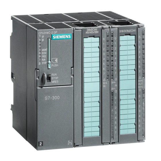
First Steps in Commissioning CPU
31xC: Positioning with digital output
SIMATIC
S7-300
First Steps in Commissioning CPU 31xC:
Positioning with digital output
Getting Started
08/2011
A5E00105533-03
___________________
Introduction
___________________
Preparation
___________________
Learning units
___________________
Further Information
1
2
3
4
Advertisement
Table of Contents


Need help?
Do you have a question about the Simatic S7-300 31xC Series and is the answer not in the manual?
Questions and answers