
Related Manuals for Z-Com XG-1020


Summary of Contents for Z-Com XG-1020
- Page 1 802.11g SOHO Wireless Access Point XG-1020 User’s Manual Version 1.0 – Novenmber 2006...
-
Page 2: Table Of Contents
Table of Content Chapter 1 Introduction..................... 3 1-1 Features and Benefits....................3 1-2 Applications......................4 Chapter 2 Hardware Installation..................5 2-1 Package Contents...................... 5 2-2 System Requirements ....................5 2-3 Mechanical Description .................... 6 2-4 Hardware Installation ....................8 2-5 Safety Notification....................9 Chapter 3 Configuring your Access Point with the Web-Based User Interface ..10 3-1 Start-up and Log in ....................10 3-1-1 Status........................10... -
Page 3: Chapter 1 Introduction
Chapter 1 Introduction The 802.11g SOHO Wireless Access Point is an AP and Bridge Mode, 2.4GHz and up to 54Mbps wireless LAN access point. The 802.11g SOHO Wireless Access Point can communicate with other mobile devices enabled for 802.11g standard-based wireless LAN connectivity. Using the card in conjunction with the 802.11g SOHO Wireless Access Point, you can create a wireless network for sharing your broadband cable or DSL Internet access among multiple PCs in and around your home or office and enjoy amazing speed of 54Mbps. -
Page 4: Applications
1-2 Applications The 802.11g SOHO Wireless Access Point offers a fast, reliable, high-speed, and high security solution for wireless clients access to the network in applications like these: Remote access to corporate network information E-mail, file transfer and terminal emulation. Difficult-to-wire environments Historical or old buildings, asbestos installations, and open area where wiring is difficult to deploy. -
Page 5: Chapter 2 Hardware Installation
Chapter 2 Hardware Installation This chapter describes initial setup of the 802.11g SOHO Wireless Access Point. 2-1 Package Contents The package you have received should contain the following items: If any of the above items are not included or damaged, please contact your local vendor for support. •... -
Page 6: Mechanical Description
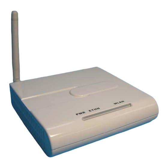
2-3 Mechanical Description Front Panel The front panel provides LED’s for device status. Refer to the following table for the meaning of each feature. 註解 [NH1]: Front Panel Picture STATUS Description 802.11g SOHO Wireless Access Point is off. PWR/SYS 802.11g SOHO Wireless Access Point is in service. Green Off No ethernet link is detected. - Page 7 Rear Panel To know the rear panel features, please refer to the following table for the meaning of each feature. 註解 [NH2]: Rear Panel Picture Power Connect the DV 12V/1.2A power supply. ONLY use the power adapter Socket supplied with the 802.11g SOHO Wireless Access Point. Otherwise, the product may be damaged.
-
Page 8: Hardware Installation
2-4 Hardware Installation Before installing the 802.11g SOHO Wireless Access Point, you should make sure that your Ethernet network is up and working with a computer. You'll be connecting the access point to the Ethernet network so that computers with 802.11g wireless adapters will be able to communicate with computers on the Ethernet network. -
Page 9: Safety Notification
Connect the Power Cable Connect the power adapter to the power socket on the 802.11g SOHO Wireless Access Point, and plug the other end of the power into an electrical outlet. Warning: We cannot assume the responsibility for the damage from using with the other power adapter supplier. -
Page 10: Chapter 3 Configuring Your Access Point With The Web-Based User Interface
Chapter 3 Configuring your Access Point with the Web-Based User Interface 3-1 Start-up and Log in In order to configure the Access Point, you must use your web browser and please do the following: 1. Type this Access Point’s address http://192.168.1.1 in the Location (for IE) or Address field and press Enter. -
Page 11: System
3-1-2 System The Device Name is used to give a name to your Access Point. This will enable you to manage your Access Point more easily if you have multiple Access Points on your network. IP Address Assigment: Allow you to setup your device ip address. You can use fixed IP address or obtain IP address automatically. -
Page 12: Wireless Setup
3-2 Wireless Setup 3-2-1 Wireless Settings The Wireless LAN Setup page lets you make changes to the wireless network settings. The Basic Settings, you can make changes to the wireless network name Operation Mode, SSID, Broadcast SSID, Wireless Mode, Channel/Frequency. The Advance Settings, you can make changes to the other advance settings, such as Output Power, Data Rate etc. - Page 13 Wireless Mode: There are three different wireless modes to operate, “Auto (11g/11b)”, “802.11b only”, and “802.11g only”. In Auto (11g/11b) mode, the access point is compatible with a mix of both 802.11g and 802.11b clients. You will see that the factory-set default “Auto (11b/11g)” will prove the most efficient.
- Page 14 DTIM Interval: This value indicates the interval of the Delivery Traffic Indication Message (DTIM). A DTIM field is a countdown field informing clients of the next window for listening to broadcast and multicast messages. When the Access Point has buffered broadcast or multicast messages for associated clients, it sends the next DTIM with a DTIM Interval value.
- Page 15 while transmitting. Note: If you complete the settings, please click on “Apply” for changes to take effect.
-
Page 16: Wireless Client
3-2-1-2 Wireless Client Select Wireless Client in the Operation Mode field to display the screen as shown next. This mode has the device act as wireless client to connect to a wireless network. Note: WPA, WPA2 and IEEE 802.1x wireless security are not available when you use Wireless Client, Bridge or AP+Repeater mode. - Page 17 Radio Enable: Turn on the wireless adapter to allow wireless communications between the device and other IEEE802.11b and IEEE802.11g compliant wireless device. Turn off the wireless adapter to stop wireless communications between the device and other IEEE802.11b and IEEE802.11g compliant wireless device. Output Power Management: Set the transmit signal strength of the access point.
-
Page 18: Bridge
3-2-1-3 Bridge The device can act as a wireless network bridge and establish wireless links with other APs. You need to know the MAC address of the peer device, which also must be in bridge mode. When twi devices connect in Bridge mode, they form a WDS (Wireless Distribution System) allowing the computers in one LAN to connect to the computers in another LAN. - Page 19 Basic Settings Operation Mode: Selecte the operating mode from the drop-down list. The options are Access Point, Wireless Client, Bridge, AP+Repeater. Channel: Select the appropriate channel from the list provided to correspond with your network settings. Wireless Mode: There are three different wireless modes to operate, “Auto (11g/11b)”, “802.11b only”, and “802.11g only”.
- Page 20 wireless network. Specifies rate of data transmission. Select the desired rate from the drop-down menu and choose “Best” to adapt the rate to the best available. Preamble Type: The Preamble defines the length of the PLCP synchronization field for communication between the Access Point and Network Card. Select the appropriate preamble type and press the Apply button to set it.
-
Page 21: Ap+Repeater
3-2-1-4 AP+Repeater Select AP+Repeater as the Operation Mode to have the device act as an access point and a wireless bridge. Basic Settings Operation Mode: Selecte the operating mode from the drop-down list. The options are Access Point, Wireless Client, Bridge, AP+Repeater. SSID: The SSID is a unique ID used by Access Points and Stations to identify a wireless LAN. - Page 22 off the broadcast of the SSID, click “No” check box next to “Broadcast SSID”. And your Access Point will refuse the connection requests from whose are not aware the Network ID. But certainly the Access Point can be easily connected well when you realize the Network ID. The default setting is “Yes”.
- Page 23 Traffic Indicator Maps, and the Traffic Indicator Message (TIM). Intra-BSS traffic: Intra-BSS traffic is trffic between wireless stations in the same BSS. Enable Intra-BSS traffic to allow wireless stations connected to the device to communicate with each other. Disable Intra-BSS traffic to only allow wireless stations to communicate with wired network, not with each other.
- Page 24 Node” problem. If the size of the packet transmitted is larger than the value you set, the RTS will be enabled. When the RTS is activated, the station and its Access Point will use a (RTS/CTS) mechanism for data transmission. The setting range is 0-2346. Fragmentation: Fragmentation mechanism is used for improving the efficiency when there is high traffic within the wireless network.
-
Page 25: Security Settings
3-2-2 Security Settings To prevent unauthorized wireless stations from accessing data transmitted over the network, the Access Point Security Settings window offers WEP features, making your data transmission over air more secure and allows you to specify Encryption Key(s) if you enable encryption for the Access Point. - Page 26 WPA2: If selected, you must configure the Radius Server Setting Screen. Note: When Operation Mode is setted in Wireless Client or Bridge mode, WPA2 can’t be setted. WPA&WPA2: If selected, you must configure the Radius Server Setting Screen. Note: When Operation Mode is setted in Wireless Client or Bridge mode, WPA&WPA2 can’t be setted.
- Page 27 A-F). Note: The WEP key must be set up exactly the same on the Wireless Access Points as they are on the wireless clients. If you set “0011223344” for the Wireless Access Point, the same WEP key “0011223344” must be assigned to other client stations. Authentication Server Authentication Server IP Address: Enter the IP address of the external authentication server in dotted decimal notation.
-
Page 28: Mac Filter
3-2-3 MAC Filter The MAC Filter allows you to restrict wireless access by MAC Address. This provides an additional layer of security. To change your device’s MAC filter settings, click MAC Filter, and select the check box of Active. Note: Be careful not to list your computer’s MAC address and select Deny the following MAC address to associate when managing the device via a wireless connection. -
Page 29: Management
3-3 Management 3-3-1 Password Setup Here allow you to change the Access Point’s password, do the following: 1. To change the current password, choose the “Change Password” option from the “Management” section in the Wireless Access Point’s left page. Key in the default password “password”... -
Page 30: Configuration File
3-3-2 Configuration File Backup Configuration: Allow to backup your current configuration to your computer. Restore Configuration: To restore your configuration from a previously saved configuration file. Back to Factory Defaults: The reset button will clear all user-entered configurations and will reset the device settings back to its factory default value. -
Page 31: F/W Upload
3-3-3 F/W Upload The Upgrade Firmware menu will display the Upgrade Firmware window so that you could update the latest firmware on the 802.11g SOHO Wireless Access Point. Please make sure that you have downloaded the latest and correct firmware from the product support website and store it in local drive before upgrading the firmware of the 802.11g SOHO Wireless Access Point. -
Page 32: Event Log
3-3-4 Logs You can view logs and alert messages in the screen. Once the log table is full, old logs are deleted as new logs are created. Refresh: Click Refresh to renew the log screen. Clear Log: Click Clear Log to clear all the logs. - Page 33 注意 ! 依據 低功率電波輻射性電機管理辦法 第十二條 經型式認證合格之低功率射頻電機,非經許可,公司、商號或使用 者均不得擅自變更頻率、加大功率或變更原設計之特性及功能。 第十四條 低功率射頻電機之使用不得影響飛航安全及干擾合法通信;經發現 有干擾現象時,應立即停用,並改善至無干擾時方得繼續使用。 前項合法通信,指依電信規定作業之無線電信。低功率射頻電機須忍 受合法通信或工業、科學及醫療用電波輻射性電機設備之干擾。...
- Page 34 Caution This device, complies with Part 15 of the FCC Rules. Operation is subject to the following two conditions: (1) this device may not cause harmful interference, and (2) this device must accept any interference received; including interference that may cause undesired operation. This Transmitter must not be co-located or operating in conjunction with any other antenna or transmitter.
-
Page 35: Limited Warranty
Limited Warranty This Warranty constitutes the sole and exclusive remedy of any buyer or reseller’s equipment and the sole and exclusive liability of the supplier in connection with the products and is in lieu of all other warranties, express, implied or statutory, including, but not limited to, any implied warranty of merchantability of fitness for a particular use and all other obligations or liabilities of the supplier. - Page 36 Please complete the information below and include it along with your products. Name: Title: Company: Telephone: Fax: Email: City/State/Zip code: Country: Product Name: Serial Number: MAC Address: Invoice Date: Product Description: If you have any further questions, please contact your local authorized reseller for support.
- Page 37 7F-2, No.9, Prosperity 1st Rd., Z-Com, Inc. Science-Based Industrial Park, Hsinchu, 300 Taiwan Tel : 886-3-5777364 Fax : 886-3-5773359 A Wireless Networking Company Product Specification XG-1020 Wireless AP/Bridge STANDARD IEEE 802.11b standard compliant IEEE 802.11g standard compliant RADIO Chipset Atheros Antenna...
- Page 38 7F-2, No.9, Prosperity 1st Rd., Z-Com, Inc. Science-Based Industrial Park, Hsinchu, 300 Taiwan Tel : 886-3-5777364 Fax : 886-3-5773359 A Wireless Networking Company MEMORY SIZE Flash 4MB (Serial Flash) SDRAM 16MB PHYSICAL SPECIFICATIONS Dimension 110mm(L)*125mm(W)*30mm(H) Weight 200g (approx.) ENVIRONMENTAL SPECIFICATIONS...
Need help?
Do you have a question about the XG-1020 and is the answer not in the manual?
Questions and answers