Table of Contents
Advertisement
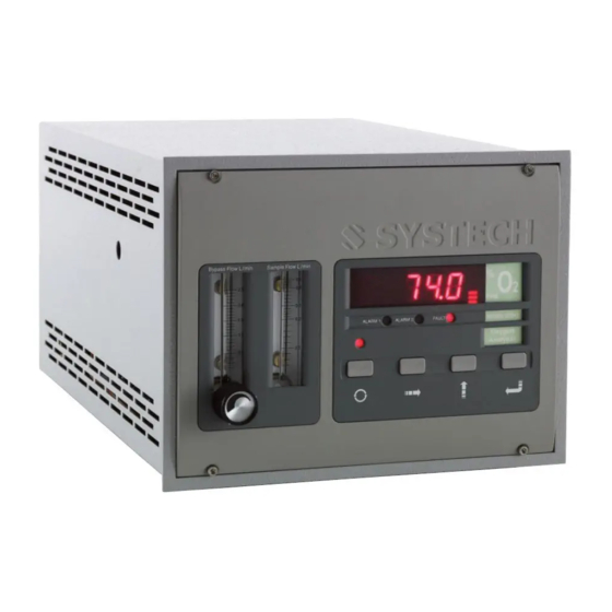
SERIES EC900
OXYGEN ANALYZERS
(Covers MK3 USB models)
OPERATOR'S INSTRUCTION
MANUAL
th
Version 4.7
5
February 2014
Illinois Instruments, Inc. (U.S.)
Systech Instruments Ltd
2401 Hiller Ridge Road
17 Thame Park Business Centre
Johnsburg
Wenman Road
Illinois IL
Thame
60051
Oxfordshire
OX9 3XA
E: support.usa@systechillinois.com
E: support.uk@systechillinois.com
www.systechillinois.com
Advertisement
Table of Contents

Summary of Contents for Systech Instruments EC900 series
- Page 1 SERIES EC900 OXYGEN ANALYZERS (Covers MK3 USB models) OPERATOR’S INSTRUCTION MANUAL Version 4.7 February 2014 Illinois Instruments, Inc. (U.S.) Systech Instruments Ltd 2401 Hiller Ridge Road 17 Thame Park Business Centre Johnsburg Wenman Road Illinois IL Thame 60051 Oxfordshire OX9 3XA E: support.usa@systechillinois.com...
-
Page 2: Table Of Contents
EC900 Series Operation Manual V4.7 Table of Contents PREFACE ..........................1 1.1 Important ............................2 INTRODUCTION ........................3 WARRANTY ..........................4 3.1 Instrument Warranty ......................... 4 3.2 Measuring Cells Warranty ........................ 4 ISOLATION VALVE OPERATING ORDER................5 PRINCIPLE OF OPERATION ....................5 TECHNICAL SPECIFICATIONS .................... - Page 3 EC900 Series Operation Manual V4.7 Appendix 2 Drawing Number 920 043_B ............... 43 Appendix 3 Drawing Number B 900 180 ................ 44 Revision History Issue Issue Date Changes 09-05-2008 Current Release Version Jon Dawson 18-08-2009 Format changes, updated some drawings...
-
Page 4: Preface
V4.7 PREFACE The EC900 series of oxygen analyzers exist with a number of variations, with different cabinet types and different measuring cells, these variations are covered in this manual. We are always trying to improve our product, of which this manual is part, so we would greatly appreciate any information you can give us of any difficulties you may encounter with the analyzer or the manual. -
Page 5: Important
EC900 Series Operation Manual V4.7 1.1 Important Please read this manual before attempting to install or operate the equipment. The equipment should be electrically connected and grounded in accordance with the instructions attached to the power cord and in accordance with good standard practice. -
Page 6: Introduction
EC900 Series Operation Manual V4.7 INTRODUCTION The EC900 Series of instruments may be supplied in three types of cabinet/housing and may use any one of four measuring cells, suitable for different applications. The instrument may also be fitted with other customer specified options. -
Page 7: Warranty
EC900 Series Operation Manual V4.7 WARRANTY 3.1 Instrument Warranty This Instrument is guaranteed for a period of one year from its delivery to the purchaser covering faulty workmanship and replacement of defective parts. This assumes fair wear and tear and usage specified on the data sheet. -
Page 8: Isolation Valve Operating Order
EC900 Series Operation Manual V4.7 WARRANTY EXCLUSION In some instances cells do not achieve their expected lifetime, failing early due to misuse: isolation valves on the analyser left open causing ingress of high oxygen levels, or cell rupture caused high pressure being applied across the cell. -
Page 9: Technical Specifications
EC900 Series Operation Manual V4.7 TECHNICAL SPECIFICATIONS Measuring Ranges: EC9x0 0.3% - 100% (All Auto-ranging) EC9x1 EC9x3 0.1ppm - 30% EC9x2 0.01ppm - 30% Calibration EC9x0 0.3% – 100% Ranges: EC9x1 EC9x3 0.1ppm – 30% EC9x2 0.01ppm – 30% EC9x0... - Page 10 EC900 Series Operation Manual V4.7 Technical Specification contd. EC9x0 Suitable Gases: All gases except corrosive gases All gases except corrosive and/or EC9x1 EC9x2 EC9x3 acidic gases Display: 4 Digit high visibility LED 1/8” OD compression (Swagelok) Sample connections: Ambient Temperature: -5°C to 50°C (Instrument and sample gas)
-
Page 11: Installation
EC900 Series Operation Manual V4.7 INSTALLATION 7.1 Instrument Installation The instrument is offered in bench/panel mount, IP66 wall mounting or rack mount. Dimensional drawings should be referred to at the rear of the manual. Please read this manual thoroughly before connecting or applying power to the unit. Systech / Illinois Instruments cannot be responsible for problems arising from improper connection or operation. -
Page 12: Gas Installation
EC900 Series Operation Manual V4.7 7.2 Gas Installation The instrument can be used to measure different oxygen concentrations. If the application is the measurement of percent oxygen, then the instrument may be connected with plastic/nylon/ptfe tubing otherwise all fittings and sample lines to the instrument should be high integrity so ensuring no ambient air is allowed to leak into the system. -
Page 13: Electrical Installation
EC900 Series Operation Manual V4.7 7.3 Electrical Installation EC91x EC93x The instrument is operated from AC line power, voltage of between 90 and 260 VAC, 50 – 60 Hz. Automatically sensed by the analyzer. The IEC standard cable supplied should be connected to a captive plug with an integral earth... -
Page 14: Instrument Operation
EC900 Series Operation Manual V4.7 INSTRUMENT OPERATION The instrument is controlled through the four digit keypad and the LED display. Control is also possible via the USB communication port. Some parameters can only be set using the USB connection. See the section on Software and the USB port In measurement mode the instrument displays the oxygen concentration of the sample gas. -
Page 15: Changing Programme Codes
EC900 Series Operation Manual V4.7 10.0 CHANGING PROGRAMME CODES Changing the programme codes in order to set up alarms, analogue outputs or other functions is simple .There are two ‘pages’ of information. Page 0 contains all the functions that the user may want to change frequently, such as setting Channel 1 analogue output from 0-100ppm to say 0-10ppm. -
Page 16: Front Panel Guide
EC900 Series Operation Manual V4.7 10.1 Front Panel Guide COMPONENT FUNCTION OPERATION Press to select the required data. First press displays the function code. After 1 second the data relating to the code is displayed. If the key is pressed... -
Page 17: Data Table Programmable Functions
EC900 Series Operation Manual V4.7 10.2 Data Table Programmable Functions There are two pages of programme functions. Page 0 are functions that the operator may want to change frequently, for example alarm trip levels and analogue output scales. Page 1 functions require a password to enter and have been arranged so that they will normally only require to be set up on commissioning. - Page 18 EC900 Series Operation Manual V4.7 10.2.1 PAGE 0 Functions DISPLAY FUNCTION PAGE Can be 0 or 1 indicating which page to move to. Sets the numerical value for the first alarm point and % or ppm. Sets the numerical value for the second alarm point and % or ppm.
- Page 19 EC900 Series Operation Manual V4.7 10.2.2 PAGE 1 Functions DISPLAY FUNCTION Sets the configuration of alarm 1 and alarm 2, i.e. high/low, low/high, low/low or high/high. Also sets whether the alarms are latched or unlatched. Should the instrument be configured with alarms and automatic calibration then...
-
Page 20: Programme Codes
EC900 Series Operation Manual V4.7 11.0 PROGRAMME CODES This function returns a two digit code to read and set up the alarm configuration. The left-hand digit sets whether alarms are high or low. See table below. FUNCTION DIGIT 1 ALARM 1... - Page 21 EC900 Series Operation Manual V4.7 If the auto-calibrate option is fitted, every x hours the calibration gas will automatically be fed to the measuring cell and after a few minutes the analyzer will self calibrate. Acd is set in hours.
- Page 22 EC900 Series Operation Manual V4.7 The factory configuration password is 1234. Be sure to make a note should you want to change the password. Should the password be lost then the password 1111 will always gain entry. ALHLD Should the instrument be configured with alarms and automatic calibration then with this function the alarms can be suppressed for the duration of the autocal and for a further five minutes until the process settles down to equilibrium.
-
Page 23: Calibration
EC900 Series Operation Manual V4.7 13.0 CALIBRATION Calibration should be carried out using a gas which is in the same range as the gas that is being analysed. For applications in the percentage range, the calibration may be carried out using atmospheric air. -
Page 24: Calibration With Certified Gas
EC900 Series Operation Manual V4.7 13.2 Calibration with Certified Gas EC9x0 EC9x1 EC9x2 Connect the certified gas to the sample port ensuring the same pressure as the sample gas, in order to obtain the same flow rate as the sample gas, allow the reading to stabilise. -
Page 25: Automatic Calibration Option
EC900 Series Operation Manual V4.7 13.3 Automatic Calibration option Automatic calibration can be initiated in two different ways. Either automatically after a pre- determined interval, or initiated by a control signal. 1. Connect the certified gas to the ‘cal gas’ connection on the rear panel of the analyzer or appropriate valve connection if using remote Autocal. - Page 26 EC900 Series Operation Manual V4.7 The instrument will only tolerate a certain level of adjustment. If the analyzer reads 4.9ppm and the certified bottle is 12.6ppm, the analyzer will reject the input of a value of 12.6ppm because it considers the error to be too large. Something else is almost certain to be incorrect. Ensure the sample from the bottle is at equilibrium and there are no leaks in the connection from the certified gas cylinder to the instrument.
-
Page 27: Usb And Rs485 Communications
EC900 Series Operation Manual V4.7 14.0 USB and RS485 COMMUNICATIONS The USB port is a bi-directional high speed communications port which allows operator intervention via a communication utility called Systech_Illinois_Client Utility. This communication utility is included on the Memory Stick supplied with the analyzer. Also supplied is a USB data connection cable. -
Page 28: Installing The Comms Utility Software
EC900 Series Operation Manual V4.7 When the driver software has installed the above window will close and you will be back at the driver installation screen. Click on “Return” and continue with the next section. 14.2 Installing the COMMS UTILITY SOFTWARE From the memory Stick distribution screen (below);... - Page 29 EC900 Series Operation Manual V4.7 After a short amount of time the following screen is displayed:- Click on OK, then the screen will change to this:- Click on the button shown above to install the Comms Utility software to the specified destination directory.
- Page 30 EC900 Series Operation Manual V4.7 This screen allows you to select or change the program group, Systech Illinois recommends that at this point you accept the default setting and click on Continue. Now the software will commence its installation process with the following screen:- The blue bar shown indicates the installation progress.
-
Page 31: Determining The Installed Comms Port
EC900 Series Operation Manual V4.7 14.3 Determining the installed Comms Port. When running the software for the first time you need to determine what the comms port is that has been assigned to the instrument. Note for multiple instruments connected simultaneously each will have a different comms port allocation. - Page 32 EC900 Series Operation Manual V4.7 Expand out the “Ports” section and you will see an entry for “USB Serial Port” this is the 900 Series analyzer. You will note that in the illustration above it has been installed as Com12. This is not suitable for Systech_Illinois_Client as it is above Com6.
-
Page 33: Running The Comms Utility Software
EC900 Series Operation Manual V4.7 Click on “Yes”, and then OK, then OK again, finally close the “Device Manager” and “Control Panel”. The comms port used by the 900 series Instrument will now be set to Com2. If multiple Instruments are to be connected simultaneously then you will have to assign a comm. Port in range Com 1 to 8 for each unit. - Page 34 EC900 Series Operation Manual V4.7 If required, check the SAVE REPLIES TO FILE box; enter a filename by either typing over DSL.Log or click on CHANGE FILE to select another. Check the INC TIME/DATE box if you wish to save the time and date with each REPLY in the file to be saved.
-
Page 35: Usb Commands For Use With The Ec900
EC900 Series Operation Manual V4.7 14.5 USB Commands For Use with the EC900 COMMAND DESCRIPTION Reads measured O value VER? Reads Version no. TEMP? Reads cell temperature SERNO? Reads instrument serial no. LIFE?X Reads cell life, X=1 for ppm cell, X=2 for % cell... -
Page 36: Rs485
EC900 Series Operation Manual V4.7 14.6 RS485 RS485 communications is available simultaneously with the USB connection. There are no user selectable links that need to be changed within the instrument, all that needs to be done is to allocate an address and connect the RS485 to the instrument. The connection details are below. -
Page 37: Optional Facilities
EC900 Series Operation Manual V4.7 15.0 OPTIONAL FACILITIES Series EC910 & EC930 Connections See Drawings B 900 150A B 900 162A. Series EC920 Connections See Drawing B 920 037 A 15.1 Analogue Outputs (Option) The analogue output option provides three outputs, each configurable for 0-10V, 4-20mA or 0-20mA (isolated) for connection to a chart recorder, computer or other device for tracking the response of the analyzer. -
Page 38: Sample Pump
EC900 Series Operation Manual V4.7 15.3 Sample Pump The sample pump option will draw a sample of gas through the instrument in the absence of a pressurised sample line. However it should be noted that especially in the case of a trace gas measuring cell there could potentially be ingress of oxygen through the exhaust line if it is vented back into a closed loop system such as a glove box etc. -
Page 39: Fault Messages/Alarms
EC900 Series Operation Manual V4.7 16.0 FAULT MESSAGES/ALARMS Certain messages may appear on the LED display of the analyzer, either in operation of the analyzer or during programming. Code Description ‘F-th’ Thermistor open circuit, most likely cause may be the cell at the rear of the instrument has become disconnected. -
Page 40: Replacing The Measuring Cell
EC900 Series Operation Manual V4.7 17.0 REPLACING THE MEASURING CELL If you are in any doubt as to how to proceed, please contact Systech / Illinois for information. 1) Switch off the analyzer at the rear panel switch and remove the mains connector. -
Page 41: Resetting The Calibration Range And Life Counter
EC900 Series Operation Manual V4.7 17.1 Resetting the Calibration Range and Life Counter After replacing a cell it is necessary to reset the required calibration range and cell life counter. This must be performed using the USB Com port and the Systech Illinois Comms Utility communications software provided. -
Page 42: Spare Parts
EC900 Series Operation Manual V4.7 18.0 SPARE PARTS Part # Description 400 006 Pcb front panel (quote serial number) 900 183 Pcb CPU (quote serial number) 900 081 Bypass flowmeter, Brass (910, 930) 900 115 Bypass flowmeter, St Steel (910, 930) - Page 43 EC900 Series Operation Manual V4.7 Measuring Cells ELECTROCHEMICAL CELL WARRANTY (CURRENT INSTRUMENTS) Part No Used In Application Description Warranty Code 900 021 EC900 Trace Cell Assy Cell Trace 900 900 028 EC900 Ultra Low Trace Assy Cell Trace Ultra Low 900...
-
Page 44: Serial Number Suffix Details
EC900 Series Operation Manual V4.7 19.0 SERIAL NUMBER SUFFIX DETAILS Systech Illinois have a process of continual development of their analyzers. Over the years there have been a number of changes in the basic instrument that have resulted in the suffix of the instrument being changed. -
Page 45: Appendix 1 Drawing Number B900-176
EC900 Series Operation Manual V4.7 Appendix 1 Drawing Number B900-176 Page www.systechillinois.com... - Page 46 EC900 Series Operation Manual V4.7 Appendix 2 Drawing Number 920 043_B Page www.systechillinois.com...
- Page 47 EC900 Series Operation Manual V4.7 Appendix 3 Drawing Number B 900 180 Page www.systechillinois.com...
Need help?
Do you have a question about the EC900 series and is the answer not in the manual?
Questions and answers