Table of Contents
Advertisement
Quick Links
hy-gain
308 Industrial Park Road
Starkville, MS 39759 USA
(662) 323-9538 FAX: (662) 323655 1
I N S T R U C T I O N M A N U A L
General Description
The "Hy-Tower" is an omnidirectional, self-
supporting vertical radiator, which operates on
10 thru 80 meters. 160 meter operation is
possible with the addition of a loading coil, as
shown in Figure 13. The "Hy-Tower" is now
supplied with stainless steel hardware.
The use of stub decoupling systems allows
band switching on 10, 15, 20, 40, and 80
Total Height
Tower Construction
Wind Survival
Hardware
Pattern Characteristics
Gain
Input Impedance
Input Power
Revision 3
Ph:
Specifications
Mechanical
Electrical
"Hy-Tower" Vertical Antenna
10,15,20,40, and 80 Meters
The stubs isolate various sections of the vertical
antenna so that an electrical 1/4-wavelength (or
odd multiple of 1/4-wavelength) exists on all
bands. On 20 meters, the 80-meter section acts
as a 3/4-wave radiator.
The tilting base of the "Hy-Tower" allows the
antenna to be completely assembled on the
ground before it is raised into position. It is
light enough for one person to assemble and for
two people to erect.
AV-18HT
53 feet (16.15m) (approximately)
Galvanized steel
75 mph (120.7 kmph)
Stainless steel
Omnidirectional
Unity on 20, 40, and 80 Meters
2dB on 10 and 15 Meters
50 ohms
1 kW AM; 2 kW PEP
Advertisement
Table of Contents

Related Manuals for Hy-Gain AV-18HT


Summary of Contents for Hy-Gain AV-18HT
-
Page 1: Specifications
AV-18HT “Hy-Tower” Vertical Antenna 10,15,20,40, and 80 Meters 308 Industrial Park Road Starkville, MS 39759 USA (662) 323-9538 FAX: (662) 323655 1 I N S T R U C T I O N M A N U A L... - Page 2 Pre-Assembly The Model 18-HT -S can be used with 50 ohm coaxial cable such as RG-213/U or RG-58A/U. NOTE: When unpacking your antenna, check Coaxial cable RG-213/U (such as BELDEN the inside of all tubing for parts. To conserve 8267) is recommended for its lower line losses space, the smaller items are sometimes put and higher power handling capabilities.
- Page 3 Install the Three (3) 1 1/4" compression clamps Assemble base assemblies "A" and "B" using onto the pipe legs and position them near the 3/8"-16 hardware. See Figure 2. insulators as 'shown in Figure 2. Tighten the clamps just enough to hold them in position. Install the three base insulator assemblies (with Refer to Figure 5 for compression clamp pipe legs attached) on the base assemblies,...
- Page 4 CAUTION Pour a standard mix of concrete (five parts sand, one part cement) into the hole until it The base assembly must be assembled reaches ground level. Vibrate the concrete level so that the tower will be vertical during the pouring to eliminate voids. when it is installed.
- Page 5 Secure the tower legs using two (2) 3/8" x 3/4" Assembly of the Tower hex bolts per splice. The nuts (12) and bolts (12) Remove the shipping straps from the tower as- are packed in the carton containing tubes and sembly.
- Page 6 Part Description Fits Tubing Sizes 358756 Clamp, Size #6 7/16",1/2", all stainless steel 5/8" and 3/4" 5/16" hex head screw Part Description Fits Tubing Sizes 358757 Clamp, Size #10 3/4", 7/8" and 1" all stainless steel 5/16 hex head screw Part Description Fits...
- Page 7 Assembly of Vertical Radiator Select the 2" x 75" length of aluminum tubing Attach one 4" metal angle to the lower -tower and place the two (2) 2" ID x 3 7/8" insulators plate and one to the upper tower plate using two over the end of the tubing which has the metal (2) 1/4"-20 x 3/4"...
- Page 8 Select a #10 tubing clamp and slip it over the Slide the 2" x 75" length of tubing (the end end of the 1 1/8" tube. Refer to Figure 5A for with the insulators attached) through the upper proper placement. and lower plate of the top tower section as shown in Figure 6.
- Page 10 Installation of 15-Meter Stub Installation of 10-Meter Stub Select a 7/16” x 60” piece of tubing and fasten Select the remaining 7/16” x 60” piece of tubing one end to one leg of the base tower section using and fasten one end to one of the remaining tower the clamps and shorting strap, as shown in Figure legs, as shown in Figure 9, using a set of leg 8.
- Page 11 Figure 8 15-Meter Stub...
- Page 13 Figure 10 Tower Leg Clamp Installation of 40-Meter Stub Select the 7/16" x 68" tube and slip it into the NOTE: Each stub must be attached to a 5/8" tube. Measure 90" for both Phone and separate tower leg. The 40-meter stub (now CW, as shown in Figure 11, then tighten the being assembled) must be attached to the very compression clamp securely.
- Page 14 Figure 11 40-Meter Stub...
- Page 15 Installation of 80-Meter Wire Select the 80-meter wire and install it in the Install the eyebolt at the tower base assembly center of the tower with the looped end at the as shown in Figure 12. Adjust for maximum top of the tower. height.
- Page 16 NOTE: To cover the low end of 80 meters (see Figure 12) it will be necessary to add a loading coil as previously explained and shown in Figure 13. This coil can be used to extend the 80 meter band or add 160 meter Figure 13 80 Meter and 160 Meter Coil Installation...
- Page 17 By adding one of two available kits, 160 meter the base assembly. Do not tighten screws at this operation can be added to the 18HT `Ey-Tower". time. these kits are available from Hy-Gain, 308 Industrial Park Road Starkville, MS 39759 WARNING USA. When installing your system, take extreme...
- Page 18 Feedline Attachment and Grounding Weatherproof the coaxial cable using Coax- Install two ground rods at each tower leg. Seal© or some similar substance to prevent Space them 24" from the leg with 18" between water from entering and ruining the coax. the two rods as shown in Figure 15.
- Page 19 Installation of Radials There is no need to make radials exactly 1/4" Since the 18-HT -S Hy-Tower is a multi-band, vertical antenna, the radial system should be wavelength long for the 18-HT-S Hy-Tower. In optimized on the lowest frequency you plan to fact, the only case where you should have 1/4"...
- Page 20 Number of Radials Length of each radial in wavelengths .125 Spacing of radials in degrees 22.5 TOTAL length of radial wire 22.5 installed, in wavelengths Power gain (dB) due to 4.0 4.7 5.2 6.0 increased efficiency Radiation take-off angle in degrees Feed-point impedance in ohms with a 1/4-wave radiating element...
- Page 21 Figure 16 VSWR Charts...
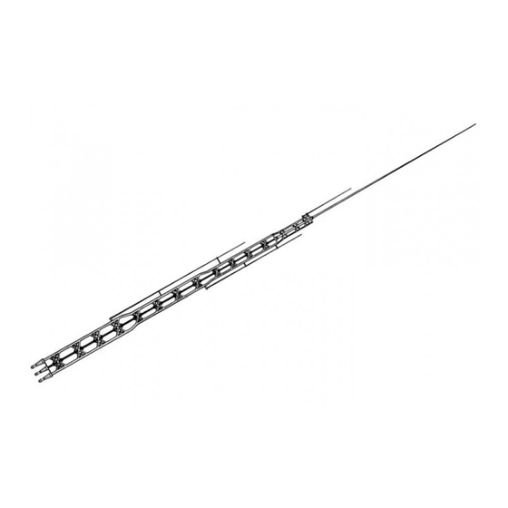
- Page 22 Figure 17 Overall View of 18-HT-S...
-
Page 23: Parts List
PARTS LIST NOTE: Item numbers may not necessarily be in numerical sequence and may appear more than one time, depending on how often a part is used or identical parts being placed in different parts packs. Item Part No. Description Qty 879810 Tower, modified, BX-24 ………………..…………………………..1 872077... - Page 24 PARTS LIST (continued) Item# Part # Description 872077 Carton, tubing and parts (continued) 872076 Parts Pack 182S, Clamps…………………………………………..1 547225 U-Bolt, 5/16" x 3" x 3 11/16"............2 161851 Clamp, Tubing, 7/16" LD..............4 163378 Strap, Shorting, 5/8" x 1 1/2"............6 163300 Clamp, Leg, formed 5/8" x 3 1/2"..........20 165123 Clamp, Compression, 1/2"..............2 171329...
- Page 25 The Hy-tower base assembly has been changed, Substitute this drawing for figure 2 on page 3.
- Page 26 The tower plates inside the Hy-tower have been improved. The new plates are made from stainless steel, Install the lower plate as shown in the diagram, One X has been left out of the top section to allow for easy installment of the lower ( larger) triangle.
- Page 27 PHASED MULTI-BAND VERTICALS for ADDITIONAL GAIN and LOW ANGLE RADIATION I N T R O D U C T I O N The following Hy-Gain verticals are well adapted for the phasing arrangements shown in this reports MODEL 18HT-S HY-TOWER...
- Page 28 The following data was experimentally derived "image antenna" or installed on the roof using on the Telex/Hy-Gain test range. Due to the a radial system. many factors that vary and influence the performance of an antenna, such as grounding...
- Page 29 When excited "out of phase" these same verti- cals can be made to give an "end fire" or bi- directional pattern in the opposite direction through the plane of the verticals. This then nulls out signals in the opposite directions. More gain is exhibited by the broadside pattern over the "end fire"...
- Page 30 SPECFICATIONS Broadside End Fire Pattern width, half power points 60 degrees 80 degrees Gain over single vertical 3.86 dB 2.3 dB Side attenuation 30 dB 20 dB Impedance 50 Ohms 50 Ohms Directional characteristics Bi-Directional Bi-Directional Figure 2 Typical Installation Phased (2) 18 HT 40 Meters 7200 KHz Design Frequency...
- Page 31 CARDIOID ARRAY (Uni-directional) When two or three identical verticals are ex- cited directly and fed 90 degrees out of phase with a spacing of 1/4 wave length, a cardioid pattern results. This pattern may be switched in either direction. By inserting a 1/4 wave length delay line the antenna will "fire"...
- Page 32 The beam pattern for two 1./4 wave length verticals will be approximately 120 degrees. An arrangement of three switchable verticals gives a 60 degree pattern in six selectable directions. Figure 4 360 Cardioid Arrangement...
-
Page 33: Radiation Pattern
E L E C T R I C A L S P E C IFICATIONS: Two Phased Verticals Three Phased Verticals Pattern Width, half power points 120 degrees 60 degrees Gain over single vertical 4.5 dB 4.5 dB Side attenuation 20 dB 20 dB Rear attenuation... - Page 34 SWITCHES & CONNECTORS OPTIONAL SPACING Various antenna spacings may be selected Low loss constant impedance type coaxial from charts A, B, and C, for single band, duo switches and connectors should be used when band or multi-band arrangements. Associated splicing phasing lines. B&W multi-position, radiations patterns for a specific spacing is single or multi-gang coaxial switches with Am- shown in Figures 1 through 5 for each band.
- Page 35 80 meter bi-directional pattern (all SW positions 3) refer to Figure 1, Part 2 "Radiation Patterns" NOTE: Due to close electrical spacing (1/4 wave) on 80 meters for Broadside (position 1) and Endure (position 2) the SVWR may be somewhat higher than 1/2 wave spacing.
- Page 36 Note: Corralate Patterns to spacing used in installation Figure 6 Radiation Patterns - Typical Spacing For Broadside And Endfire Arrangements...
Need help?
Do you have a question about the AV-18HT and is the answer not in the manual?
Questions and answers