Advertisement
Quick Links
308 Industrial Park Road
Starkville, MS 39759 USA
(662) 323-9538 FAX: (662) 323-6551
INSTRUCTION MANUAL
General Description
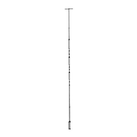
The Hy-Gain 14AVQ/WB-S is an omnidirec-
tional, self-supporting, vertical radiator that
operates in the 10, 15, 20, and 40 meter
amateur bands. The system will work against
earth ground or a resonant radial system when
mounted above ground. You can make your
own radial system following the manual, or
use the Hy-Gain 14RMQ Radial System Kit
available at your Hy-Gain dealer.
The antenna can be used for either Phone or
CW with either a ground or roof mount. It can
also be tuned to mid-band for use with either
Phone or CW. In either case, the SWR band
widths of the antenna are broad enough that
the antenna will operate at an SWR of 2:1 or
less from 10 to 40 meters. The 14AVQ/WB-S
is supplied with stainless steel hardware and
element clamps for all electrical and most
mechanical connections.
Ph:
M o d e l A V - 1 4 A V Q
Four Bands Vertical Antenna
10, 15, 20, 40 Meter
Theory of Operation
The use of heavy duty "Hy-Q Traps" provides
automatic band selection. The Hy-Q Traps
are parallel resonant circuits which isolate
the various sections of the antenna and give
quarter wavelength resonance on all bands.
The
top
hat
enhances
characteristics of the antenna and permits the
antenna to be shortened by top loading it.
WARNING
When
installing
extreme' care t o
contact with'' power l i n e s or overhead
obstructions. F a i l u r e
care could result in serious or fatal
i n j u r y .
FOR OUR OVERSEAS CUSTOMERS: The
United States used English units of measure-
ments. Please see page 12 of this manual for
assistance in identifying the hardware and
components supplied with this product.
the
broad-band
your
system,
take'
avoid any accidental
to exercise this
Advertisement

Subscribe to Our Youtube Channel
Related Manuals for Hy-Gain AV-14AVQ


Summary of Contents for Hy-Gain AV-14AVQ
- Page 1 Hy-Gain 14RMQ Radial System Kit antenna to be shortened by top loading it. available at your Hy-Gain dealer. WARNING The antenna can be used for either Phone or...
- Page 2 Since the 14AVQ/WB-S is a multi-band, above ground, a resonant radial system must vertical antenna, the radial system should be be used, such as Hy-Gain's 14RMQ Radial optimized on the lowest frequency you plan System Kit. If the antenna is roof mounted to use.
- Page 3 Table 1 Optimum Ground System Configurations Phase Verticals for Assembly and Installation Before you begin, read the instructions and Two or more 14AVQ/WB-S antennas may be study the illustrations. Compare the parts phased together to produce gain or directivity over one antenna. Refer to the Engineering against the Parts List.
- Page 4 Figure 1 Antenna Assembly Dimensions...
- Page 5 Tubing After adjustment of the tubing lengths, tighten Select the proper size tube clamps as shown in the clamp with a 5/16 inch nut driver, socket, the chart. When installing the clamps, place or open end wrench until the tubing will not the clamp near the tube end with the top of the twist or telescope.
- Page 6 15-Meter Trap and M3 CAUTION Section Assembly All of the antenna dimensions must be set Place two, untightened #10 tubing clamps on the mode chosen - all CW, all mid- (Item No. 17) over the 1" x 8" long M3 section band or all phone.
- Page 7 Top Hat Refer to Figure 3, Radial Top Hat Assembly, in assembling the Top Hat Push a 1/8" caplug (Item No. 19) on the end of each top radial (Item No. 1). Installing the Antenna Refer to the mounting details in Figure 4 and AO-385S-A-007 5 to install the completed antenna.
- Page 8 If you are roof mounting your antenna, use four (4) sets of 1/4"-20 hardware for the preceding step. Before tightening them, attach two adjacent radials to each set of hardware as shown in Figures 3 and 5. If desired, you may use the four, 33 foot (10.058 m) radial system shown.
- Page 9 NOTE: RADIAL DIMENSIONS MEASURED FROM BASE TO INSULATOR. PREFERRED SYSTEM ALTERNATE SYSTEM Item No. Description ALL RADIALS 33' (10.058 m) FROM BOLT TO INSULATOR Bolt, hex head, 1/3"-20 x 3/4" Lockwasher, internal, 1/4" Figure 5 Nut, hex, 1/4"-20 Guying Details...
- Page 10 Figure 6 Completed Installation of 14AVQ/WB-S Hooking Up The Antenna 2. Because every antenna installation is influenced by the soil conditions and the Connect your coax (RG-213/U) to the SO- proximity effect of nearby objects, the 239 connector at the bottom of the mounting dimensions in the manual must be fine bracket.
- Page 11 20-meter band, as well as the remaining bands available, depending For maximum lightning protection, we upon the model involved. recommend the use of a Hy-Gain LA-1 Lightning Arrestor, available from your Hy- Your antenna is now ready to use.
- Page 12 PARTS LIST Item Part No. Description Qty 173499 Radial Top Hat ................3 871049 Base Assembly, 14AVQ ..............1 (not used) 190900 Tube, M1, 11/4" x 48", slotted ............1 463056 Insulator, upper ................1 523057 Screw, hex head, #10-24 x 1"............1 190303 Tube, M2, 11/8 x 52"...
- Page 13 Converting English Measurement to Metric Use this scale to identify lengths of bolts, diameters of tubes, etc.. The English inch (") and foot (') can be converted to centimeters in this way. 1 inch (1") = 2.54 cm 1 foot (1) = 30.48 cm Example:...
- Page 14 PHASED MULTI-BAND VERTICALS for ADDITIONAL GAIN and LOW ANGLE RADIATION I N T R O D U C T I O N The following Hy-Gain verticals are well adapted for the phasing arrangements shown in this reports MODEL 18HT-S HY-TOWER...
- Page 15 The following data was experimentally derived "image antenna" or installed on the roof using on the Telex/Hy-Gain test range. Due to the a radial system. many factors that vary and influence the performance of an antenna, such as grounding...
- Page 16 When excited "out of phase" these same verti- cals can be made to give an "end fire" or bi- directional pattern in the opposite direction through the plane of the verticals. This then nulls out signals in the opposite directions. More gain is exhibited by the broadside pattern over the "end fire"...
- Page 17 SPECFICATIONS Broadside End Fire Pattern width, half power points 60 degrees 80 degrees Gain over single vertical 3.86 dB 2.3 dB Side attenuation 30 dB 20 dB Impedance 50 Ohms 50 Ohms Directional characteristics Bi-Directional Bi-Directional Figure 2 Typical Installation Phased (2) 18 HT 40 Meters 7200 KHz Design Frequency...
- Page 18 CARDIOID ARRAY (Uni-directional) When two or three identical verticals are ex- cited directly and fed 90 degrees out of phase with a spacing of 1/4 wave length, a cardioid pattern results. This pattern may be switched in either direction. By inserting a 1/4 wave length delay line the antenna will "fire"...
- Page 19 The beam pattern for two 1./4 wave length verticals will be approximately 120 degrees. An arrangement of three switchable verticals gives a 60 degree pattern in six selectable directions. Figure 4 360 Cardioid Arrangement...
- Page 20 E L E C T R I C A L S P E C IFICATIONS: Two Phased Verticals Three Phased Verticals Pattern Width, half power points 120 degrees 60 degrees Gain over single vertical 4.5 dB 4.5 dB Side attenuation 20 dB 20 dB Rear attenuation...
-
Page 21: Installation
SWITCHES & CONNECTORS OPTIONAL SPACING Various antenna spacings may be selected Low loss constant impedance type coaxial from charts A, B, and C, for single band, duo switches and connectors should be used when band or multi-band arrangements. Associated splicing phasing lines. B&W multi-position, radiations patterns for a specific spacing is single or multi-gang coaxial switches with Am- shown in Figures 1 through 5 for each band. - Page 22 80 meter bi-directional pattern (all SW positions 3) refer to Figure 1, Part 2 "Radiation Patterns" NOTE: Due to close electrical spacing (1/4 wave) on 80 meters for Broadside (position 1) and Endure (position 2) the SVWR may be somewhat higher than 1/2 wave spacing.
- Page 23 Note: Corralate Patterns to spacing used in installation Figure 6 Radiation Patterns - Typical Spacing For Broadside And Endfire Arrangements...
Need help?
Do you have a question about the AV-14AVQ and is the answer not in the manual?
Questions and answers