Table of Contents
Advertisement
Quick Links
308 Industrial Park
Starkville, MS 39759 USA
(662) 323-9538 FAX: (662) 323-6551
INSTRUCTION MANUAL
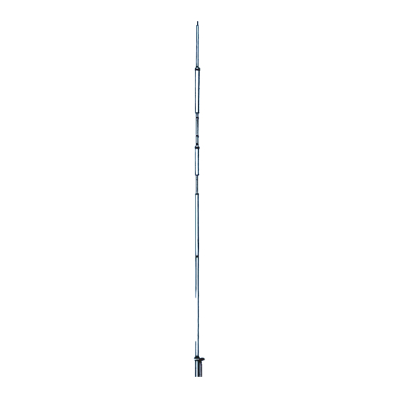
General Description
This vertical antenna is designed for operation
on 10, 15 and 20 meters. It is designed to
work against earth ground or a radial ground
system. When used in conjunction with a
resonant radial system, the vertical antenna
becomes very efficient with a low angle of
radiation and excels in DX communications.
A simulated radial ground system (Model 14
RMQ, Order No. 184) is available from your
Hy-Gain dealer. This manual tells you how to
construct
your own
12AVQ-S
now
features
hardware
for
all
mechanical connections.
NOTE: If you mount the antenna, then find the
roof space is too small for the radial system,
you can droop the radials over the roof at
almost any angle without seriously changing
the performance of the antenna.
Ph:
radial
system. The
stainless
steel
electrical
and
most
AV-12AVQ
Triband HF Vertical
10, 15, 20-Meter
WARNING
When installing your system, take extreme
care to avoid any accidental contact with
power lines or overhead obstructions.
Failure to excise this care could result in
serious or fatal injury.
Construction
It is designed to fit a 15/8" mast. A 11/4"
plumbers pipe has a 1 5/8" outside diameter
and is highly recommended for masting
material. This is the-- minimum roasting
material which will meet the severe weather
survival specifications of this antenna. The
warranty, is void if a lighter mast is used.
The Model 12AVQ-S is made of high quality
seamless aluminum tubing for maximum
strength. The Hy-Q traps are durable and
highly weather resistant.
Advertisement
Table of Contents

Related Manuals for Hy-Gain AV-12AVQ


Summary of Contents for Hy-Gain AV-12AVQ
- Page 1 It is designed to fit a 15/8" mast. A 11/4" RMQ, Order No. 184) is available from your plumbers pipe has a 1 5/8" outside diameter Hy-Gain dealer. This manual tells you how to and is highly recommended for masting construct...
- Page 2 Unpack the parts and check them against the SWR and Feedline Parts List and drawings. The Model 12AVQ-S antenna is designed to match 50 ohm coaxial transmission line. By Determine where to mount your antenna following our detailed instructions and (rooftop or ground) and what mode of measuring accurately, an SWR of 1.2:1 or transmission to use (Phone or CW).
- Page 3 Select the proper size tubing clamp as shown Select the base assembly (Item No. 4) and the in the chart. When installing the clamps, place #16 compression clamp (Item No. 8) Slip it the clamp near the tube end with the top of the on the end of the base assembly.
- Page 4 Select the M2 section (Item 1) and slip it into Carefully recheck all dimensions - then the base assembly. Measure Dimension 'Was tighten all compression clamps securely. shown in Figure 3 according to your mounting location and mode of transmission. Now Place the 7/16"...
- Page 5 Figure 3 Overall view with Callouts and Dimensions...
- Page 6 Ground your radial system by connecting the If the antenna is ground mounted, install as base of the antenna to proper ground using shown in Figure 4. Ground the base of the an- #10 or larger copper or aluminum wire. A tenna as described above.
- Page 7 Figure 6 Radial Arrangement...
- Page 8 Figure 7 Schematic of Antenna Base Figure 8 Completed Roof Mount Installation of the 12AVQ...
- Page 9 A. If it favors the low end, shorten the 10 meter adjustment one inch (1") or no Final Adjustment for Setting the 12AVQ-S, more than 1 1/2 inches. Run another 14AVQ-S and 18AVT-S Antennas VSWR measurement. You will now have an indication of how far the 1.
- Page 10 PARTS LIST Item Part No. Description 190605 M3, 1" x 6 1/2"................1 178416 M4, 7/16" x 28 3/4" ..............1 877128 Base Assembly................1 877132 Trap, 10 Meter................l 878417 Trap, 15 Meter................1 872012-1 Parts Package 384S, Stainless Steel ........…..1 358756 Clamp, #6 tubing .................1 358758 Clamp, #16 tubing ...............1 358757 Clamp, #10 tubing..............:.3 455644 Caplug, 7/16 ....:............1...
- Page 11 PHASED MULTI-BAND VERTICALS for ADDITIONAL GAIN and LOW ANGLE RADIATION I N T R O D U C T I O N The following Hy-Gain verticals are well adapted for the phasing arrangements shown in this reports MODEL 18HT-S HY-TOWER...
- Page 12 The following data was experimentally derived "image antenna" or installed on the roof using on the Telex/Hy-Gain test range. Due to the a radial system. many factors that vary and influence the performance of an antenna, such as grounding...
- Page 13 When excited "out of phase" these same verti- cals can be made to give an "end fire" or bi- directional pattern in the opposite direction through the plane of the verticals. This then nulls out signals in the opposite directions. More gain is exhibited by the broadside pattern over the "end fire"...
- Page 14 SPECFICATIONS Broadside End Fire Pattern width, half power points 60 degrees 80 degrees Gain over single vertical 3.86 dB 2.3 dB Side attenuation 30 dB 20 dB Impedance 50 Ohms 50 Ohms Directional characteristics Bi-Directional Bi-Directional Figure 2 Typical Installation Phased (2) 18 HT 40 Meters 7200 KHz Design Frequency...
- Page 15 CARDIOID ARRAY (Uni-directional) When two or three identical verticals are ex- cited directly and fed 90 degrees out of phase with a spacing of 1/4 wave length, a cardioid pattern results. This pattern may be switched in either direction. By inserting a 1/4 wave length delay line the antenna will "fire"...
- Page 16 The beam pattern for two 1./4 wave length verticals will be approximately 120 degrees. An arrangement of three switchable verticals gives a 60 degree pattern in six selectable directions. Figure 4 360 Cardioid Arrangement...
- Page 17 E L E C T R I C A L S P E C IFICATIONS: Two Phased Verticals Three Phased Verticals Pattern Width, half power points 120 degrees 60 degrees Gain over single vertical 4.5 dB 4.5 dB Side attenuation 20 dB 20 dB Rear attenuation...
- Page 18 SWITCHES & CONNECTORS OPTIONAL SPACING Various antenna spacings may be selected Low loss constant impedance type coaxial from charts A, B, and C, for single band, duo switches and connectors should be used when band or multi-band arrangements. Associated splicing phasing lines. B&W multi-position, radiations patterns for a specific spacing is single or multi-gang coaxial switches with Am- shown in Figures 1 through 5 for each band.
- Page 19 80 meter bi-directional pattern (all SW positions 3) refer to Figure 1, Part 2 "Radiation Patterns" NOTE: Due to close electrical spacing (1/4 wave) on 80 meters for Broadside (position 1) and Endure (position 2) the SVWR may be somewhat higher than 1/2 wave spacing.
- Page 20 Note: Corralate Patterns to spacing used in installation Figure 6 Radiation Patterns - Typical Spacing For Broadside And Endfire Arrangements...
Need help?
Do you have a question about the AV-12AVQ and is the answer not in the manual?
Questions and answers