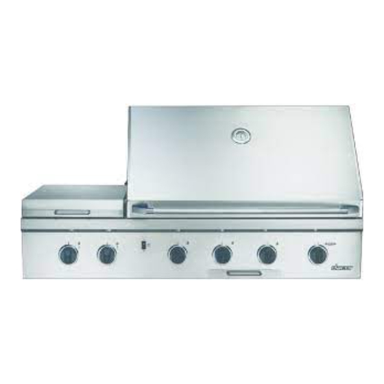
Dacor Epicure EOG36 Installation Instructions Manual
Hide thumbs
Also See for Epicure EOG36:
- Installation instructions (1 page) ,
- Use & care manual (13 pages) ,
- Use and care manual (12 pages)

Related Manuals for Dacor Epicure EOG36


Summary of Contents for Dacor Epicure EOG36
- Page 1 n sta ll at I o n n struc t I o n s ® pI cu r E ut d o o r r I ll For use with models EOG303, EOG36, EOG52, EOSB162 Part No. 65249 Rev. F...
-
Page 2: Table Of Contents
Common sense, caution and care must be exercised WARNING when installing, maintaining or operating appliance. WARNING – Hazards or unsafe practices which COULD result Always contact Dacor about problems or conditions you do not in severe personal injury or death. understand. CAUTION CAUTION –... - Page 3 18. This appliance should be serviced only by supplier or your fire department. qualified service personnel. Contact the nearest Dacor authorized servicer at (800) 793-0093, or FOR YOUR SAFETY at www.Dacor.com for examination, repair or Do not store or use gasoline or other flammable adjustment.
-
Page 4: Design Specifications
esign peCifiCaTions Product Dimensions 6" x 6" (152mm x 152mm) Utility Cutout 25" (635mm) 21" (533mm) 3/8" (10mm)ø Both sides EOG30 - 21" (533mm) EOG36/52 - 28" (711mm) 12" (305mm) Min. to combustibles above the countertop surface 2" (51mm) EOSB162 & EOG303/36/52 4 1/4"... -
Page 5: Installation Specifications
nsTallaTion peCifiCaTions Verifying the Package Contents A MINIMUM clearance of 1/4 inch (6.4mm) must be maintained, inside the base enclosure below the Verifying the Package Contents countertop material, from all vertical surfaces on EOG303/36/52 Models the sides of the outdoor grill. •... - Page 6 nsTallaTion peCifiCaTions Connections, which may be disturbed when installing the cylinder NOTE: in the enclosure can be leak tested inside the enclosure. The rotisserie mounting bracket on the right side of the grill chassis and the slot in the right side Internal mounting means shall be provided on the outdoor gas grill finish trim must line up for proper rotisserie motor for mounting the LP-gas supply cylinder.
-
Page 7: Gas And Electrical Supply Requirements
nsTallaTion peCifiCaTions Gas and Electrical Supply Electrical Supply Requirements Requirements The EOG outdoor grills are factory-equipped with a three-prong, grounding plug. WARNING Correct voltage, frequency and amperage must be supplied to the Electrical grounding instructions: appliance from an isolated, grounded circuit which is protected by This outdoor cooking gas appliance is equipped with a properly sized circuit breaker or time-delay fuse. -
Page 8: Gas Supply Requirements
nsTallaTion peCifiCaTions WARNING Gas Supply Requirements The maximum gas supply pressure to the regulator must not exceed 1/2 pound per square inch. Verify proper gas supply has been provided. Refer to Tabe 1, Page 6. Do not apply excessive pressure when tightening connections and fittings. - Page 9 Install the bolts, then return the left side drawer to its location. NOTES: Before installing the right side roll out tank drawer, Install The Dacor cart ships assembled ready for the the regulator and hose on the grill drawer for final gas EOG Outdoor Grill installation assembly.
-
Page 10: Gas Connections
6. Place the tank into the final position within the base enclosure or cart. The Dacor outdoor cooking products ship with a 3/4 inch nipple, regulator, and 1/2” reducer for gas supply connections. NOTE: The Dacor outdoor grills are approved for installation Install a 3/4 inch (19mm) or 1/2 inch (13mm) natural gas supply on typical whole-house LP gas supply systems. -
Page 11: Verifying Proper Operation
LP tank control valve and contract The grill or cooktop must be isolated from the gas your authorized Dacor service agent to schedule a service call. supply piping by closing the shut-off valve during When installed properly, the flame will be steady and quiet. -
Page 12: Electrical Schematics
nsTallaTion nsTRuCTions Electrical Schematics INDICATOR LIGHTS 3-PRONG PLUG SUPPLY CORD & STRAIN RELIEF FOR OUTDOOR USE BK BK 4 POINT RE-IGNITER 2VA, 120VAC 60Hz TERMINAL BLOCK S4 S3 3-PRONG PLUG ROTISSERIE BOX DIAGRAM 10W, 12V 10W, 12V IGNITION LEFT HALOGEN LIGHT RIGHT HALOGEN LIGHT PLUGS SUPPLY CORD &... - Page 13 nsTallaTion nsTRuCTions INDICATOR LIGHTS 3-PRONG PLUG SUPPLY CORD & STRAIN RELIEF FOR OUTDOOR USE L1 BK BK BK 3 2 1 6 POINT RE-IGNITER TERMINAL BLOCK 120VAC, 2VA, 60Hz 3-PRONG PLUG ROTISSERIE BOX DIAGRAM 10W, 12V 10W, 12V LEFT HALOGEN LIGHT RIGHT HALOGEN LIGHT SUPPLY CORD &...
-
Page 14: Service Information
If you need service, be sure to have the model and serial numbers when you call. You’ll find these numbers on the serial number plate located on the light shield in the fresh food compartment. Contact a Dacor authorized servicer, a Dacor dealer, or the Dacor Customer Service Department at (800) 793-0093. - Page 16 Specifications contained within are subject to change without notice. No liability is assumed by DACOR for changes in specifications. The information and images in this book are the copyright property of Distinctive Appliances, Inc. Neither this book nor any information or images contained herein may be copied or used in whole or in part without the express written permission of Distinctive Appliances, Inc.
Need help?
Do you have a question about the Epicure EOG36 and is the answer not in the manual?
Questions and answers