
Subscribe to Our Youtube Channel
Related Manuals for REMKO MVX Series


Summary of Contents for REMKO MVX Series
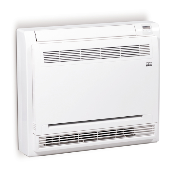
- Page 1 Operating and installation instructions REMKO MXV series Compact wall chest for MVV outdoor units MXV 221, MXV 361, MXV 451 0207-2019-01 Edition 1, en_GB Read the instructions prior to performing any task!
- Page 2 Read these operating instructions carefully before commis- sioning / using this device! These instructions are an integral part of the system and must R410A always be kept near or on the device. Subject to modifications; No liability accepted for errors or mis- Refrigerant prints! Translation of the original...
-
Page 3: Table Of Contents
Table of contents Safety and usage instructions......................4 1.1 General safety notes........................4 1.2 Identification of notes........................4 1.3 Personnel qualifications........................4 1.4 Dangers of failure to observe the safety notes................4 1.5 Safety-conscious working....................... 4 1.6 Safety notes for the operator......................5 1.7 Safety notes for installation, maintenance and inspection.............. -
Page 4: Safety And Usage Instructions
REMKO MXV series Safety and usage instructions CAUTION! This combination of symbol and signal word 1.1 General safety notes warns of a potentially hazardous situation, which if not avoided may cause injury or mate- Carefully read the operating manual before com- rial and environmental damage. -
Page 5: Safety Notes For The Operator
"certificate of warranty" to conditions stipulated in this manual and comply REMKO GmbH & Co. KG at the time when the with all applicable regional regulations. units are purchased and commissioned. -
Page 6: Transport And Packaging
REMKO MXV series 1.11 Transport and packaging The devices are supplied in a sturdy shipping con- tainer. Please check the equipment immediately upon delivery and note any damage or missing parts on the delivery and inform the shipper and your contractual partner. For later complaints can not be guaranteed. -
Page 7: Technical Data
Technical data 2.1 Unit data Series MXV 221 MXV 361 MXV 451 Wall chest for MVV outdoor units for cooling and Operating mode heating Nominal cooling output Nominal heat capacity Application area (room volume), approx. Adjustment range, room temperature °C +17 to +30 Operating range °C/r.H.%... -
Page 8: Unit Dimensions
REMKO MXV series 2.2 Unit dimensions Fig. 1: Unit dimensions MXV 221-451 (All measurements in mm) 1: Mounting plate We reserve the right to modify the dimensions and design as part of the ongoing technical development process. -
Page 9: Design And Function
The indoor unit consists of a fin evaporator, evapo- The following settings apply for manual operation: rator fan, controller and condensate tray. The indoor unit can be combined with REMKO outdoor Pressing once: Automatic mode, units from the MVV 1200 -2000 DC range that pro- Pressing twice: Cooling test mode, active for 30 vide sufficient combination options. - Page 10 REMKO MXV series Connection of the optional wired remote con- trol KFB-3 The wired remote control, type KFB-3, can be con- Alarms are indicated by a code (see chapter nected to the devices of the series MXV 221-451. Troubleshooting and customer service).
-
Page 11: Display On Indoor Unit
4.2 Display on indoor unit 4.3 Manual air distribution Display Setting the air distribution The vertical air control blades can be manually moved to the left and right (s. Fig. 6). An automatic swing function is also available for horizontal air distribution (s. - Page 12 REMKO MXV series Fig. 7: Opening front panel Fig. 8: Blow-off direction switch 1: Blow-off direction switch A: Switch setting [A] B: Switch setting [B] Automatic selection of the blow-out side Operating mode Cooling mode Heating mode The unit blows out...
-
Page 13: Keys On The Remote Control
4.4 Keys on the remote control “Mode” key Operating mode selection (Auto ⇒ Cooling ⇒ Heating ⇒ Dehumidification ⇒Recirculation) “Arrow down” key Decreases the selected temperature or timer set- tings. "On/Off" key Switches the unit on or off. "Display" key Switches the display of the indoor unit on or off (if fitted). - Page 14 REMKO MXV series “Swing” key Low-noise operating mode Switches the automatic upward and downward Appears when the Low-noise operating mode is movement of the air discharge fin on and off. active. “Eco” key Unit status Turns the power save mode on (if fitted).
- Page 15 Select the operating mode and temperature Individually adjusting the air discharge fin Press the key several times to select the Use the key to move the air discharge desired operating mode. The selection fin to 5 different positions. appears on the display of the IR remote con- trol.
- Page 16 REMKO MXV series Switching the indoor unit display off Energy saving function This function enables the display illumination of the If the unit is in the cooling or heating mode, the indoor unit to be switched off. energy saving function can be activated with the IR...
- Page 17 Activate/deactivate delayed switching on and Activating the “Cooling only” function The IR remote control is factory programmed for The unit switch-on delay can be activated the cooling and heating functions. The “Cooling only” function can be activated or deactivated by with the key.
- Page 18 REMKO MXV series Manual unit addressing 2. Assigning the unit address The MVV series outdoor units automatically assign If the addressing mode (see above) is active, the addresses to the indoor units during commis- signal transmission must be activated by pressing sioning.
- Page 19 Changing the parameters for fan functions Selectable parameters Pressing the keys simultaneously Parameter Definition for 5 seconds displays the parameter level on the IR remote control. 7 fan stages, temperature incre- ments of 0.5 °C 3 fan stages, temperature incre- ments of 1.0 °C 7 fan stages, temperature incre- ments of 1.0 °C (factory setting)
-
Page 20: Installation Instructions For Qualified Personnel
REMKO MXV series Installation instructions Minimum clearances for qualified personnel Observe the minimum clearances to allow access for maintenance and repair work and facilitate Important notes prior to installation optimum air distribution. Observe the operating manuals for the indoor unit and the outdoor unit when installing the entire system. -
Page 21: Installation
Installation Connection of refrigerant piping The refrigerant pipes should be connected by the customer on the right-hand inner side of the unit. NOTICE! It may be necessary to fit a reducer or flared adapter to the indoor unit. These fittings are Installation should only be performed by author- included with the indoor unit as an accessory kit. -
Page 22: Condensate Drainage Connection And Safe Drainage
REMKO MXV series Condensate drainage Safe drainage in the event of leakages connection and safe Local regulations or environmental laws, for example the German Water Resource Act (WHG), drainage can require suitable precautions to protect against uncontrolled drainage in case of leakage to provide... -
Page 23: Electrical Wiring
Electrical wiring 8.1 General notes Make the connection as follows: Open the air inlet grill. A protected power supply cable is to be connected to the outdoor unit and a four-core control line with Remove the covers on the right-hand side a minimum cross-section of 1.5mm . -
Page 24: Electrical Wiring Diagram
REMKO MXV series 8.2 Electrical wiring diagram MCC-1 MVV 1200-2000 DC Controller X Y E L1 L2 L3 N P Q E Off Co. On 230V/1~/50 Hz Ext. On/Off 400 V/3~/50 Hz MXV (G) MXV (B) MXV (A) C…D…E…F P Q E... - Page 25 Connection of optional condensate pump KP 6/KP 8 L(1) 2(N) L(1) 2(N) N PE Fig. 17: Electrical wiring diagram Outdoor unit Condensate pump supply Indoor unit Condensate pump fault contact Condensate pump KP 6/KP 8 BK: black Power supply WH: white...
-
Page 26: Dip Switch, Functions
REMKO MXV series 8.3 DIP switch, functions Switch Function Setting Description S W1 The cooling request is terminated when the measured tempera- ture actual value is equal to the set temperature setpoint value (factory setting Control behav- SW1_1 iour in cooling... - Page 27 DIP switch functions (continued) Switch Function Setting Description S W5 The fan does not run when the heat exchanger fluid tempera- ture is 15 °C or colder (factory setting) S W5 The fan does not run when the heat exchanger fluid tempera- ture is 20 °C or colder Cold air avoid- ance in heating...
-
Page 28: Electrical Drawings
REMKO MXV series 8.4 Electrical drawings Fig. 18: Electrical drawings Control board Electronic E-valve Display board Fin motors Power supply Contact for liquid level switch Connection option accessories Colour codes: Communication line from outdoor unit Black: Black Connection option accessories... -
Page 29: Commissioning
Commissioning Final tasks Re-install all disassembled parts. Familiarise the operator with the system. NOTICE! Commissioning should only be performed by specially trained personnel and documented after the certificate has been issued. Observe NOTICE! the operating manuals for the indoor unit and Check that the shut-off valves and valve caps outdoor unit when commissioning the entire are tight after carrying out any work on the... -
Page 30: Troubleshooting And Customer Service
REMKO MXV series Troubleshooting and customer service The unit and components are manufactured using state-of-the-art production methods and tested several times to verify that they function correctly. However, if malfunctions do occur, please check the functions as detailed in the list below. For systems with an indoor unit and outdoor unit, refer to the chapter "Trouble- shooting and customer service"... - Page 31 Operational malfunctions (continued) Malfunction Possible causes Checks Remedial measures Filter is dirty/air inlet/ Have the filters been Clean the filters outlet opening is blocked cleaned? by debris Windows and doors Have structural/usage Close windows and open. Heating/cooling modifications been doors/install additional load has increased made? units...
- Page 32 REMKO MXV series Error codes Code Description Mode conflict Communication fault between outdoor unit and indoor unit Probe fault, indoor air (T1) Probe fault, evaporator (T2) Probe fault, suction pipe (T2B) Fan motor malfunction -EEPROM malfunction Malfunction of the electronic injection valve...
-
Page 33: Care And Maintenance
Care and maintenance Regular care and observation of some basic points This enables you to ensure the operational reli- will ensure trouble-free operation and a long ability of the plant at all times! service life. For systems which operate year-round (e.g. in DANGER! server rooms), the maintenance intervals must be reduced accordingly. - Page 34 REMKO MXV series Cleaning the filter Disconnect the power supply to the unit. Open the front side of the unit by folding the grill down/forwards (Fig. 19). Pull the filter out in an upwards direction (Fig. 19). Clean the filter with a commercially available vacuum cleaner.
-
Page 35: Exploded View Of The Unit And Spare Parts List
Exploded view of the unit and spare parts list 12.1 Exploded view of the unit Fig. 22: Exploded view drawing We reserve the right to modify the dimensions and design as part of the ongoing technical development process. -
Page 36: Spare Parts List
REMKO MXV series 12.2 Spare parts list IMPORTANT! To ensure the correct delivery of spare parts, please always the device type with the corresponding serial number (see type plate) No. Designation Mounting plate Infrared remote control Fan impeller Fan motor... -
Page 37: Shutdown
REMKO GmbH & Co. KG or your contractual residual humidity from the unit. partner will be pleased to provide a list of certified Shut down the system using the remote con- firms in your area. -
Page 38: Index
REMKO MXV series Index Remedial measures ....30 Manual air distribution ....11 Air distribution, manual . - Page 40 REMKO QUALITY WITH SYSTEMS Air-Conditioning | Heating | New Energies Telephone +49 (0) 5232 606-0 REMKO GmbH & Co. KG Hotline within Germany +49 (0) 5232 606-0 Klima- und Wärmetechnik Telefax +49 (0) 5232 606-260 Im Seelenkamp 12 E-mail info@remko.de...
Need help?
Do you have a question about the MVX Series and is the answer not in the manual?
Questions and answers