Table of Contents
Advertisement
Quick Links
Advertisement
Table of Contents

Related Manuals for BIRO EMG-32


Summary of Contents for BIRO EMG-32
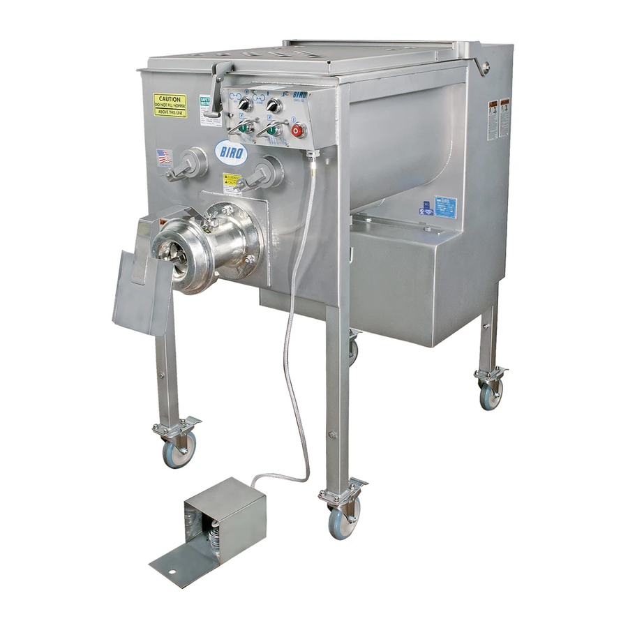
- Page 1 Model EMG-32 Ergonomic Mixer-Grinder/Chopper Operating Manual and Parts List IMPORTANT NOTICE This Manual contains important safety instruction which must be strictly followed when using this equipment. Item No. EMG92099 Form No. EMG32MAN-4-18-12 B...
-
Page 2: Table Of Contents
TABLE OF CONTENTS: PAGE NOTICE TO OWNERS AND OPERATORS ..........SAFETY TIPS . -
Page 3: Notice To Owners And Operators
No one should use or service this machine without proper training and supervision. All operators should be thoroughly familiar with the procedures contained in this Manual. Even so, BIRO cannot anticipate every circumstance or environment in which its products will be used. You, the owner... -
Page 4: Safety Tips
NEVER Alter This Machine From its Original Form as Shipped From Factory. DO NOT Operate Machine With Missing Parts. • PROMPTLY REPLACE Any Worn or Illegible Warning Labels. • ALWAYS Read Operation and Service Manual BEFORE Operating, Cleaning, or Servicing. • USE ONLY BIRO Parts and Accessories Properly Installed. -
Page 5: Installation
NEVER Operate Without all Warning Labels Attached and Owner/Operator Manual Available to the Operator. • USE ONLY BIRO Parts and Accessories Properly Installed. UNCRATING AND SET UP 1. Read this Manual thoroughly before installation and operation. Do not proceed with installation and operation if you have any questions or do not understand anything in this Manual. - Page 6 8. The size of the electrical wiring required from the power source to the mixer-grinder/chopper is a MINIMUM OF No. 10 WIRE. 9. The BIRO Manufacturing Company is not responsible for permanent wiring, connection or installation. NOTE TO OWNER AND ELECTRICIAN: IF THIS MACHINE IS NOT CORD...
-
Page 7: Operation
15. Check placement of all warning labels and Manual. Machine is now ready for trained operators to process product. 16. Use meat deflector attached to grinding bowl to eliminate meat splatter. 17. Contact your local Distributor or BIRO directly if you have any questions or problems with the installation or operation of this machine. OPERATION TO AVOID SERIOUS PERSONAL INJURY •... -
Page 8: Grinder Knife & Plate Do's & Don'ts
OPERATION (Continued) • NEVER Open Machine During Operation. • DO NOT Wear Gloves While Operating. • DO NOT Tamper With, Bypass, Alter, or Modify This Equipment in Any Way From Its Original Condition. • NEVER Operate Machine With Product Mixer Safety Cover Open or Removed or Magnetic Interlock Switch By-Passed. -
Page 9: Maintenance
PROMPTLY REPLACE Any Worn or Illegible Warning Labels. • USE ONLY GENUINE BIRO Parts and Accessories Properly Installed. A. GRINDING BOWL INSTALLATION 1. Mount the grinding bowl on the two threaded studs on the front of the machine. Tighten in position with provided nuts. -
Page 10: Chain Tension
B. LUBRICATION continued Recommended types of chain lubricant are those with Molybdenum Disulphide or Graphite added. Also bonded lubricants such as Dow Corning Molykote 321R or equivalent are excellent for open chains. The lubricant should be of a viscosity whereby it will “flow” somewhat and penetrate the internal working surfaces. -
Page 11: Operator's Notes
D. MAIN DRIVE CHAIN TENSION (Continued) To Tighten Chain Tension. Turn motor adjusting studs clockwise. Be sure to turn both adjusting studs the same amount and evenly. Total chain flex should be ⅛ to ⅜”. Do not overtighten chain as this will put excessive and damaging pressure on the motor bearings. -
Page 12: Optional Eagle Drive Belt Tensioning Instructions
OPTIONAL EAGLE BELT DRIVE SYSTEM FORCE TABLE #1-7 7-1/2 HP (5.6 kw) new 15.3 lb (6.9 Kg) used 11.2 lb (5.1 Kg) - Page 13 “EAGLE” DRIVE SYSTEM Tensioning Instructions Note- The “Eagle” drive belts do not stretch. However, there is a “break-in” period where the teeth in the belt “mesh” with the teeth of the sprockets during the 1 few hours of operation. The belt should be re-tensioned after 1 week of operation, according to this tensioning procedure. No further maintenance is required after this initial adjustment.
-
Page 14: Operator's Notes
- OPERATOR’S NOTES -... -
Page 15: Grove Gear Reducer Replacement & Lubrication
REPLACING MORSE GEAR REDUCER Mixer Paddle Gear Reducer Retro-Fit Effective with Model EMG-32; Serial No. 6988, April 2007 The Mixing Paddle Gear Reducer, Item No. EMG20301 (Winsmith) has been replaced with an alternate Gear Reducer, Item No. EMG20301G (Grove) If an old style Winsmith Gear Reducer, #EMG20301, should need replacing, a “Retrofit Kit” will be supplied incorporating the new Grove Reducer, Item No. - Page 16 LUBRICATION FOR GROVE GEAR REDUCER 1. Factory Filling The speed reducers are oil filled at the factory to the proper level for the standard mounting position. The oil level should be checked and adjusted (if necessary) prior to operation, using the oil level plug provided and while the unit is oriented in its operating position.
- Page 17 EMG20301G-R GROVE GEAR REDUCER LUBRICATION AND MAINTENANCE AFTER SERIAL No. 6987 LUBRICANTS FOR EMG20301G-R GROVE GEAR WORM REDUCER The precision-made gears and bearings in Grove Gear Speed Reducers require high-grade lubricants of the proper viscosity to maintain trouble-free performance. For best results, use lubricants on the following chart for worm gear reducers.
-
Page 18: Mixer Drive Shaft Seal Replacement
#53953, MIXER DRIVE SHAFT SEAL REPLACEMENT l. Clean the inside of the groove of the mixer drive shaft seal and mating contact surface of the tub wall thoroughly with scotch-bright or a roughing pad. 2. Dispense a small amount of #454 Loctite adhesive to both these areas - assure even coverage. 3. -
Page 19: Cleaning
Electrical Components. • ALWAYS Thoroughly Clean Equipment at Least Daily. CLEANING THE EMG-32 MIXER-GRINDER l. Disconnect mixer grinder from power-source and perform lockout/tagout procedures. 2. Remove grinding bowl end ring, breaker plate, knife and grinding auger. 3. Remove mixing paddles by first loosening the wing nuts locking the mixing paddle from hubs. Turn the front hubs clockwise and remove from front of machine. -
Page 20: Mixing Paddle: Installation; S/N's 6001 To 6057
MIXING PADDLE INSTALLATION S/N’s 6001 to 6057 The Mixing Paddles ARE NOT INTER- CHANGEABLE, however they are timed to allow for proper mix action. PADDLE INSTALLATION: Install the corresponding mixer paddles by matching the male and female hub drives with the respective female and male paddle hubs. -
Page 21: Mixing Paddle History By Serial Number
MIXING PADDLE HISTORY BY SERIAL NUMBER... -
Page 22: Electric Footswitch Parts List & Diagram
ELECTRIC FOOT SWITCH 53693-E 53693-D 53693-O 53693-H 52655 53693-M 53693-X 53693-A 52654 52661 53693-F 53693-C 53693-G 224-2 53693-I 53693-X 53693-T 53693-U 53693-W FOOT SWITCH PARTS LIST 224-2 Cord connector, wt, straight, ¾” 52654 Male plug w/ 6’ cord, 5 wire 52655 Female receptacle, 5 pole 52661... -
Page 25: Pneumatic Footswitch Parts List & Diagram
OPTIONAL PNEUMATIC FOOT SWITCH #56304 Part No. DESCRIPTIONS 56300BEL Bellow, Replacement 56300C Guard Only 56300K-CPB CPB Coupling Metal Body-Male 56303 Foot Switch w/Male Coupling 56304 Foot Switch Assembly Complete ⅜ HHS004S Hex Head Screw, #8 - 32 x HN05S Hex Nut #8 - 32 LW03S Lock Washer #8 PNEUMATIC FOOT SWITCH ASSEMBLY... -
Page 28: Electrical Subplate Components
ELECTRICAL SUBPLATE COMPONENTS Part No. Description Part No. Description 226EE-OL01.9G EMG90584 Overload, B18K-G, 1.3-1.9AMP, 440-460V Timer- on delay 226EE-OL4I EMG90675 Overload, B18K-I, 2.5-4 AMP, 208-240V Reversing contactor- 24 volt 35241 EMG92003-1 Mounting bracket Subplate electrical EMG92014 35374 Terminal block Fuse block EMG92016 35375 End barrier... -
Page 29: Parts List, Not Shown Parts
Wire nut, yellow EMG92015 Wire nut, red Din rail, 11 inches long EMG92016 Bowl Nut Wrench, ¾”, w/ chain EMG-32 Operating Manual 53583 EMG92099 Decal, “Caution Do Not Fill Above Line” Warning label, English 53687 H653-E Cord connector 10/4 AL... -
Page 30: Parts List
7 14 26 27 Fig. Description Fig. Description Item No. Item No. EMG20050-06 #40 roller chain ¼ Sq x 1 ” Spur gear key EMG62136 EMG20050-01 #40 chain connecting link 40B36F 1” sprocket EMG82029 Grove gear reducer assembly Sealed bearing EMG20301G EMG82032 ¼... - Page 31 14 15 Fig. Description Fig. Description Item No. Item No. Hex head screw ⅜-16 x 2, SS Hex Nut, -18, SS HHS086S HN19S Flat washer, .397 x 1¼ x .120 thk. SS Spacer, Lid lock arm shoulder bolt EMG92032 EMG62204 Sleeve Bushing Shoulder bolt, ⅜...
- Page 32 54303 EMG62200 14688 Description Description Item No. Item No. Auger motor shim Knife drive pin EMG62010 HK48 Adjustable leg weldment Hex nylock nut ⅜-16, SS EMG62035 HNNL25S Hopper weldment Hex nut 5/16-18, SS EMG62050 HN19S Male paddle assembly- LH Hex flange nut ½-13, SS (3 req.) EMG62072 HNF42S Female paddle assembly- RH...
-
Page 33: Belt Drive Option
Fig. Description Item No. Product Mixer Safety Cover, SS EMG62168 Round Head Screw, ¼-20 x 1”, SS RHS31S Safety Cover Latch EMG62102 Hex Nut, Nylon Insert, ¼-20, SS HNNL15S BELT DRIVE OPTION Hex Head Screw ½-13 x 2”, SS Main Driven Sprocket, Eagle 140 Tooth HHS129S H383-EAGL up to S/N: 7682... - Page 34 EMG62012 #40 Roller chain w/ master link EMG20050-06 EMG20050-01 #40 Chain connecting link 40B36F x 1” bore sprocket EMG82029 Set screw, -18 x ½” SSS26 EMG-32 GRIND Fig. Description Item No. Start pushbutton, Green 42MC-Y73 Switch guard, SS 50655-2 3 Position, Selector Switch, Paddle direction...
-
Page 35: Journal Box Assembly Parts Diagram- Right Hand Hinge Assembly
ITEM No. 53886 JOURNAL BOX ASSEMBLY 53888 53785 53785 53889 53609 not shown LW35S 53724 53939 53940 HHS153S Item No. Description Item No. Description 53886 53889, 53939 Rear bearing cup/cone assembly Journal box assembly Use H311A 53609 Journal box housing Grease fitting ⅛... -
Page 36: Standard Equipment
STANDARD EQUIPMENT EMG20699-1 Multiple Lug Dolly w/ 5” Casters/Brakes (Lugs not supplied) SAFETY LABEL LOCATIONS KEEP HANDS OUT OF HOPPER... - Page 37 SAFETY LABELS #EMG92033 #H653-E #H653-SP CAUTION DO NOT FILL HOPPER ABOVE THIS LINE 53687 -NOT TO SCALE- #53687 SAFETY INSTRUCTIONS CUIDADO CAUTION #EMG92028 #EMG62198 #56315 #BES16971 #53783...
-
Page 39: Operator Signature Page
OPERATOR’S SIGNATURE PAGE WARNING READ AND UNDERSTAND THIS ENTIRE MANUAL BEFORE SIGNING BELOW MY SIGNATURE ATTESTS THAT I HAVE COMPLETELY READ AND UNDERSTAND THIS MANUAL. I REALIZE THAT THIS MACHINE, IF OPERATED CARELESSLY, CAN CAUSE SERIOUS INJURY TO MYSELF AND OTHERS. NAME (PRINT) SIGNATURE SUPERVISOR’S... -
Page 40: Limited Warranty
The warranty card must be returned to The BIRO Manufacturing Company for proper registra- tion. If no warranty card is returned to BIRO, the warranty period will begin from the date the machine was originally shipped from the factory.
Need help?
Do you have a question about the EMG-32 and is the answer not in the manual?
Questions and answers