Table of Contents
Advertisement
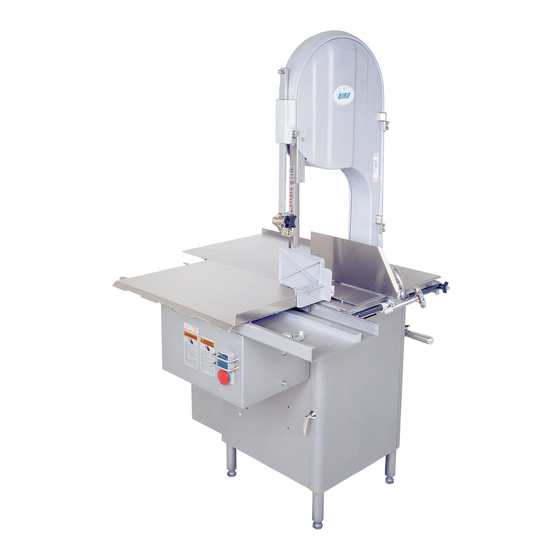
MODEL 3334 & 3334-4003 SERIES POWER MEAT SAW
OPERATING AND SERVICE MANUAL
REVISED - SERIAL No.1,000 ON
SQ. BASE #35323 ON
FLAT TOP #35323 ON
3334SS
3334SS-4003
IMPORTANT NOTICE
This Manual contains important
safety instructions which must
be strictly followed when using
this equipment.
No. 16313-100-5-18-40 B
Advertisement
Table of Contents

Related Manuals for BIRO 3334SS


Summary of Contents for BIRO 3334SS
- Page 1 MODEL 3334 & 3334-4003 SERIES POWER MEAT SAW OPERATING AND SERVICE MANUAL REVISED - SERIAL No.1,000 ON SQ. BASE #35323 ON FLAT TOP #35323 ON 3334SS 3334SS-4003 IMPORTANT NOTICE This Manual contains important safety instructions which must be strictly followed when using this equipment.
-
Page 3: Table Of Contents
TABLE OF CONTENTS PAGE NOTICE TO OWNERS AND OPERATORS ..........SAFETY TIPS . -
Page 4: Notice To Owners And Operators
Warnings related to possible damage are indicated by: BIRO also has provided a wall chart to be posted near the equipment. If any warning label, wall chart, or Manual becomes misplaced, damaged, or illegible, please contact your nearest Distributor or BIRO directly for a replacement. -
Page 5: Safety Tips
BEFORE Removing Shrouds, Removable Guards, Covers, Doors, Fences or Panels for Cleaning, Servicing or Any Other Reason. NEVER Leave Machine Unattended While the Saw is Running. PROMPTLY REPLACE Any Worn or Illegible Warning Labels. USE ONLY BIRO Parts and Accessories Properly Installed. -
Page 6: Installation
NEVER Operate Without all Warning Labels Attached and Wall Chart Posted. NEVER Leave Machine Unattended While the Saw is Running. USE ONLY BIRO Parts and Accessories Properly Installed. 1. Read this Manual thoroughly before installation and operation. Do not proceed with installation and operation if you have any questions or do not understand anything in this Manual. - Page 7 5. The drive belt is packed loose in machine to prevent deformation, and must be installed on pulleys at time of wiring motor. 6. The BIRO Manufacturing Company is not responsible for permanent wiring, connection or installations. NOTE TO OWNER AND ELECTRICIAN: IF THIS MACHINE IS NOT CORD...
-
Page 8: Warning Labels For Power Saws
16. Check placement of all warning labels, wall chart and Manual. Machine is ready for trained operators to process product. 17. Contact your local Distributor or BIRO directly if you have any questions or problems with the installation or operation of this machine. -
Page 9: Operation
OPERATION SHARP MOVING BAND TYPE SAW BLADE TO AVOID SERIOUS PERSONAL INJURY ONLY Properly Trained Personnel Should Use This Equipment. ALWAYS Keep Hands Clear of Band Type Saw Blade and Other Moving Parts. NEVER Operate with Saw Guard on Saw Guide Bar in the Raised Position or the Saw Guard Removed from the Saw Guide Bar. - Page 10 6. ALWAYS use the Safety End Cut Pusher Plate (Part No. 256P) for smaller products or the last cuts of product. “C” The pusher plate is supplied as standard on all BIRO power saws. 7. When finished cutting, push stop button. Perform lockout/tagout procedure.
-
Page 11: Wall Chart (Part No. 671)
ITEM NUMBER 671 WALL CHART “BAND SAW SAFETY GUIDELINES” ATTACH TO WALL IN VICINITY OF MACHINE IN EASY VIEW OF OPERATOR. -
Page 12: Operator's Notes
OPERATOR’S NOTES... -
Page 13: Cleaning
Electrical Components. ALWAYS Thoroughly Clean Equipment at Least Daily. CLEANING THE BIRO POWER SAW: Disconnect electrical power to the machine before cleaning. Parts to be removed have been made accessible and can be removed without tools. Notice in the drawing below that all parts are numbered. Each part should be removed for cleaning in the numbered sequence shown. -
Page 14: Maintenance
NEVER Bypass, Alter, or Modify This Equipment in Any Way From It’s Original Condition. PROMPTLY REPLACE Any Worn or Illegible Warning Labels. USE ONLY GENUINE BIRO Parts and Accessories Properly Installed. A. GENERAL 1. Machine should be generally inspected every time it is cleaned (at least daily) to ensure that it is in good condition and has not been damaged or tampered with. -
Page 15: Lubrication
Safety end cut pusher plate is with machine and accessible. All warning labels are present, properly affixed and legible. Model and Serial Number plate is properly affixed and legible. Wall poster within operators view from machine. Manual accessible to operator. USE BIRO No. 374 GREASE FOR RE-GREASING SEE INSTRUCTIONS BELOW B. LUBRICATION: 1. -
Page 16: Motor Adjustment
TO S/N 27958 C. SAW GUIDE BAR AND SAW GUARD: The factory recommends that when service is performed on any BIRO SAW the servicing agency be sure that the BIRO SAW is equipped with the most current safety features available. - Page 17 15/16 1/4” Nut & Lock Washer, Outside DRILL THIS HOLE 1st 9/32 DIAMETER Attach with bolt, lock washer & nut to door, INSIDE THEN DRILL THIS HOLE 2nd 9/32 DIAMETER THROUGH FLANGE 1/4” Nut & Lock Washer, INSIDE KEEP PARALLEL Inside Head Door Flange GUARD...
-
Page 18: Longer Saw Guard Kit
LONGER SAW GUARD KIT Item No. 663K This longer guard is for replacement on existing saws. Install the new guard with the ¼” diameter screws supplied with the Saw Guard Kit, Item No. 663K. - Page 19 LONGER SAW GUARD KIT Item No. 16662K This longer guard is for replacement on existing saws. Install the new guard with the ¼” diameter screws supplied with the Saw Guard Kit, Item No. 16662K.
-
Page 20: Base Door Hinge System
BASE DOOR HINGE SYSTEM The Base Door Hinge System on the Model 3334 Series has been changed from an internal “plate and pin” system to an external “barrel and pin” system. Effective Serial Numbers: Old Style New Style Hinged Base Door with Internal Hinged Base Door with External Hinge Plates, #S16217R Hinge Plates, #S16217R-2... -
Page 21: New Design "Flat Top" Base
NEW DESIGN “FLAT TOP” BASE Beginning with Serial No. 35323 on August 11. 1999, the Model 3334 and 3334-4003 base structure has been redesigned. The ” offset (step down) on the front-top of the base for the stationary bar has been deleted. The base top now “flat”... - Page 23 SPLIT PLATTER ASSEMBLY...
- Page 24 A16005 Head & Door Assembly A16006 HEAD DOOR ASSEMBLY LW15S (3) A71-1 UPPER WHEEL 71-1 HINGE BRACKET HHS050S (3) HN15S 16006 ASSEMBLY SSS15S 16005 LW10S AS16014U HEAD DOOR HINGE ASSEMBLY-UPPER 14GP 661-1-DECA S16014U HHS025S S16014L-2 112-212 LW10S HN15S HHS025S HHS035S LW10S HHS035S 16112...
- Page 25 A16003U335-6 OR A16003UDF335-6 (SERIAL NO. 22164 ON) UPPER WHEEL ASSEMBLY WITH HINGE PLATE A16003U-6 OR A16003UDF-6 (SERIAL NO. 22164 ON) UPPER WHEEL ASSEMBLY WITHOUT HINGE PLATE A247-1 UPPER SHAFT BEARING ASSEMBLY WITHOUT WHEEL S16335X 16003U-6 S252X 230DL HHS010S HN35S A227 BEARING CUP/ CONE ASSEMBLY A227...
- Page 26 Item No. Description A19-1 Ratchet assembly FW07S Flat washer, ⅜ SS HHS040S Hex head screw, ¼-20 x ¾ HN15S Hex nut, ¼-20 SS HN35S Hex nut, -16 SS ⅜ LW10S Lock washer, SS Ratchet trigger, SS S189 Ratchet arm stud, SS Ratchet base, SS 10-1 Ratchet arm...
- Page 27 Item No. Description A295 Wheel cleaner assembly AS16290 Cleaning unit total assembly AS16Z Guide bracket saw cleaner assembly, SS FW06S Flat washer, ¼ SS HHS003S Hex head screw, 8-32 x ¼ SS HHS004S Hex head screw, 8-32 x ⅜, SS HHS009S Hex head screw, 10-24 x ¼, SS HHS025S...
- Page 28 AS16132 REAR STEEL A415D CLEANER ASSEMBLY STATIONARY BAR ASSEMBLY S119A 119A S268 415D LW10S HN15S Item No. Description Item No. Description A415D N/A, use AS415D AS130 Saw cleaner assembly, SS HN15S Hex nut, ¼-20 SS AS16132 Rear saw blade cleaner assembly, SS LW10S Lock washer, ¼...
- Page 29 STANDARD 3334 MEAT CARRIAGE & CHANNEL Item No. Description Item No. Description A16155 16155 Meat carriage assembly complete Meat carriage top & angle only A175S Thumb guard assembly 16155-13 Carriage stop angle SS, welded FW06S 16155-2A Flat washer, ¼ SS Meat carriage guide AN15S Acorn nut, ¼-20 SS...
- Page 30 OPTIONAL 3334 EZ FLOW MEAT CARRIAGE & CHANNEL Item No. Description Item No. Description A16155EZ S155EZ-3 Meat carriage assembly complete - EZ Flow Hex stand-off, EZ Flow carriage A175S Thumb guard assembly 16155EZ Meat carriage top & angle only AN15S 16155EZ-1 Acorn nut, ¼-20 SS Meat carriage top only w/ weld studs (DNS)
- Page 31 STANDARD ON 3334-4003 EZ FLOW MEAT CARRIAGE & CHANNEL ALSO OPTIONAL ON ALL OTHER 3334 A181155EZ MEAT CARRIAGE ASSEMBLY EZ FLOW Item No. Description A175S Item No. Description Thumb guard assembly A181155EZ Meat carriage assembly, EZ Flow S181155AEZ Meat carriage angle - EZ Flow AN15S S18155EZ-1 Acorn nut, ¼-20 SS...
-
Page 32: Motor Covers
S16217L S16217LTP BASE DOOR, LEFT TAPERED PANEL, SS BASE DOOR LEFT, SS USE WITH Motor Mfg. Model No. Specifications Doerr 73032 1-1/2HP, 115/230-50-1 open U.S. Motor G57347 1-1/2HP, 115/230-50-1 open Doerr 72933 1-1/2HP, 115/230-60-3 open Baldor L3605 2HP, 115/230-60-1 TE Baldor L3605-50 2HP, 115/230-50-1 TE... - Page 33 REMOVAL and INSTALLATION for Self-Centering Lower Removable Wheels ALWAYS Turn Off, Unplug Machine From Power Source and Perform Lockout/Tagout Procedure to the Machine BEFORE Cleaning or Servicing. Follow disassembly procedures in the Cleaning Section of the Operating and Service Manual. Removal of the Lower Wheel will be the last procedure.
- Page 34 Item No. Description Item No. Description A16547 14740 Lower bearing housing assembly, Retaining ring - external w/o wheel 14746 T-handle lock, removable lower wheel A363 Lower bearing cup/cone assembly 16251-11X78AL Pulley, 11.4 x ⅞ aluminum HN25 Hex nut, ⅜-16, carbon-plated 16251-90X78AL Pulley, 9 x ⅞...
- Page 35 LOWER REMOVABLE WHEEL INSTALLATION AND REMOVAL INSTRUCTIONS ALWAYS Turn Off, Unplug Machine From Power Source and Perform Lockout/Tagout Procedure to the Machine BEFORE Cleaning or Servicing. Follow disassembly procedures in the Cleaning Section of the Operating and Service Manual. Removal of the Lower Wheel will be the last procedure. REMOVAL Loosen Item No.
- Page 36 A609AAW-16 SWITCH ASSEMBLY 241WH Item No. Description 241BL A16226A Green/red switch button assembly w/ springs 224 & 259 A609AAW-16 Switch assembly, 1& 3 ph, less heater coils 340 (3) H462-2 Guard for switch toggle 224 & 259 HN10S (3) H462A Guard assembly for switch toggle 226-28 HHS010S...
- Page 37 WATERTIGHT MAGNETIC SWITCH ASSEMBLIES (AEG) INCLUDES MOUNTING BRACKET AND WIRES Item No. Description Item No. Description A22616EE-514 BAEG/MS-PB/05-C8 2HP 208-220-50/60-3 A22616EE-530 BAEG/MS-PB/05-F3.2 2HP 550/575-3 A22616EE-516 BAEG/MS-PB/05-E4.7 2HP 440/460-3 A22616EE-534 BAEG/MS-PB/05-E6.3 3HP 440/460-60-3 A22616EE-518 BAEG/MS-PB/05-D4.7 1.5-2HP 380/415-50-3 A22616EE-536 BAEG/MS-PB/05-D8 3HP 380-60-3 A22616EE-522 BAEG/MS-PB/05-C14 3HP 220-230-50/60-3 A22616EE-538 BAEG/PC-PB/05-F4.7 3HP 550-60-3 A22616EE-5221 BAEG/MS-PB/05-CS14 1.5HP 208/230-50/60-1...
-
Page 38: Wiring Diagrams
2HP BALDOR MOTOR: M65-L3605-B... - Page 39 2HP BALDOR MOTOR: M66-35M388X966-B 2HP BALDOR MOTOR: M65-L3605-B 3HP BALDOR MOTOR: M72-36L153Y129-B...
- Page 40 2HP BALDOR MOTOR: M65-L3605T-50-B 2HP BALDOR MOTOR: M66-35M388X966-B...
- Page 41 2HP WEG MOTOR: M68-218T3E145TW...
- Page 42 3HP US ELECTRIC/EMERSON MOTOR: M701-G57011-U 2HP WEG MOTOR: M68-M3558T-50-B...
- Page 43 2HP WEG MOTOR: M68-218ET3E145TW 2HP BALDOR MOTOR: M68-M3558T-50-B...
- Page 44 2HP BALDOR MOTOR: M68-M3558T-50-B...
-
Page 45: Parts List/Ordering
MODEL 3334 PART NUMBERS AND DESCRIPTIONS MODEL & SERIAL NO. REQUIRED WHEN ORDERING PARTS Item No. Description Item No. Description AN15S Acorn nut, ¼-20, SS Ratchet base, SS FW06S Flat washer, ¼, SS S200B1 Stop stud, guide bar & carriage stop FW07S S229 Flat washer, ⅜, SS... - Page 46 PART NUMBERS AND DESCRIPTIONS (CONT.) Item No. Description Item No. Description 16200 264-1S Carriage stop movable Hand wheel shim 16212 Platter latch 264G Hand wheel groove pin 16220-1 Carriage stop fixed Meat gauge release cotter pin 16226A-9 271AL Switch button speed nut Meat gauge worm gear 16232 272-7-1...
-
Page 47: Parts Assemblies List/Ordering
Item #260 slide gib. From Ser. # 25060 to Ser. #36251 the machined blocks were eliminated and the slide gibs redesigned to a dovetail configuration to secure the head. (The Factory Does Not Recommend Field Conversions) PARTS EXCLUSIVE TO 3334SS WITH OPTIONAL STAINLESS STEEL HEAD STRUCTURE Item No. Description Item No. -
Page 48: Wearable Saw Parts List
WEARABLE SAW PARTS THAT WILL FIT BIRO POWER CUTTERS Item No. 16159 1433-34-3334-44-55 CARRIAGE BEARING 1433-34- SAW CLEANER BRACKET STEEL BLADE CLEANER CARRIAGE BEARING ALL SAWS ALL SAWS 11-22-33 MODELS MODELS CARRIAGE BEARING 1433-34-3334-44-55 ALL SAWS ALL SAWS 11-22-33 11-22-1433-33-34-3334-44-4436-55... -
Page 49: Warning Label Locations On Machine
WARNING LABEL LOCATIONS ON MACHINE ATTACH ON HEAD STRUCTURE BELOW MODEL/SERIAL NUMBER TAG Item No. 653PC-E ATTACH TO CHANNEL BRACKET NEXT Item No. 653PC-SP TO SWITCH BUTTONS... - Page 50 WARNING LABEL LOCATIONS ON MACHINE ITEM NO. 710 “BLADE TENSION” ITEM NO. 708 “DANGER EXPOSED DECAL BLADE” DECAL ATTACHED TO HEAD ATTACHED TO SAW GUARD ON DOOR AS SHOWN SAW GUIDE BAR ATTACH TO HINGED RIGHT BASE DOOR ITEM NO. 16716 “CAUTION”...
-
Page 51: Operator's Signature
OPERATOR’S SIGNATURE PAGE WARNING READ AND UNDERSTAND THIS ENTIRE MANUAL BEFORE SIGNING BELOW MY SIGNATURE ATTESTS THAT I HAVE COMPLETELY READ AND UNDERSTAND THIS MANUAL. I REALIZE THAT THIS MACHINE, IF OPERATED CARELESSLY, CAN CAUSE SERIOUS INJURY TO MYSELF AND OTHERS. NAME (PRINT) SIGNATURE SUPERVISOR’S... -
Page 52: Limited Warranty
The warranty card must be returned to The BIRO Manufacturing Company for proper registra- tion. If no warranty card is returned to BIRO, the warranty period will begin from the date the machine was originally shipped from the factory.
Need help?
Do you have a question about the 3334SS and is the answer not in the manual?
Questions and answers