
Related Manuals for horsch Partner 2000 FT


Summary of Contents for horsch Partner 2000 FT
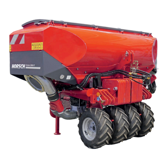
- Page 1 OPERATING INSTRUCTIONS Partner 2000 FT TRANSLATION OF THE ORIGINAL OPERATING INSTRUCTIONS READ CAREFULLY PRIOR TO STARTING UP! KEEP OPERATING INSTRUCTIONS IN A SAFE PLACE! ART.: 8062 0203 ISSUE: 01/2019...
- Page 3 HORSCH: ..............Confirmation of receipt of machinery Warranty claims become only effective when the first use of the machine is reported to HORSCH Maschinen GmbH within a week. www.horsch.com under SERVICE PARTNERBEREICH an interactive PDF form is available for down- load for this purpose (not available in all languages).
- Page 4 HORSCH Maschinen GmbH Sitzenhof 1 D-92421 Schwandorf hereby declares that the product Front hopper Type: Partner 2000 FT this declaration refers to, conforms with all relevant fundamental health and safety requirements of the EC directive 2006/42/EC. Schwandorf, 22/01/2019 Klaus Winkler...
-
Page 6: Table Of Contents
Table of contents Introduction ...........4 Operation .............26 Foreword ............4 Commissioning / Tractor change ....26 Notes on representation .........4 Connecting/Parking ........27 Service............5 Connecting ...........27 Warranty claim processing ......5 Transport position .........28 Consequential damage........5 Parking ............29 Use in the field ..........30 Safety and responsibility ......6 Checks before and during use on the field .. - Page 7 Waste disposal ...........53 Appendix .............54 Tightening torques ........54 Selecting the metering auger .....56 Electronics configuration ......67 Overview............67 Work and speed signal .........72 Index ............75...
-
Page 8: Introduction
DANGER to the safety notes! Highlights a danger that will lead to death or HORSCH will not assume liability for any dam- severe injury if it is not avoided. age or malfunctions resulting from failure of complying with the operating instructions. -
Page 9: Service
Service Consequential damage The machine has been manufactured by HORSCH Company would like you to be com- HORSCH with greatest care. However, despite pletely satisfied with your machine and our the intended use deviations in placing quantity services. up to total failure may be caused by e.g.:... -
Page 10: Safety And Responsibility
HORSCH does not assume any liability for Please read and comply with the following safety damages resulting from the unintended use of notes, before you start to use the machine! the machine. -
Page 11: Qualification Of Personnel
Furthermore, for certain activities the corre- sponding personnel must have been trained by The person must be physically able to keep service personnel from HORSCH. This refers to ¾ the machine under control. the following activities: The person is able to perform work with the ¾... -
Page 12: Children In Danger
Children in danger Safety in traffic Children are not able to assess dangers and may DANGER behave unpredictably. Children are therefore especially endangered: No passengers are allowed to ride on the machine! Keep children away from the machine. ¾ Especially before drive off and before trigger- ¾... -
Page 13: Safety In Operation
The machine must only be put into operation ¾ after receiving instructions by employees of Coupling and uncoupling the authorized dealer or a HORSCH em- ployee. Faulty coupling of the machine to the three-point The machine registration form must be com- ¾... - Page 14 Hydraulics Technical limiting values If the technical limiting values of the machine The hydraulic system is under high pressure. are not complied with, the machine may sustain Escaping fluid can penetrate the skin and cause damage. This can lead to accidents with severe serious injuries.
-
Page 15: Fertiliser And Dressed Seed
Structural changes and extensions must only ¾ be made in an authorized workshop or by an operator who has been trained by HORSCH. Inappropriate handling of fertiliser and dressed Comply with country-specific instructions for seed can cause poisoning and death. -
Page 16: Care And Maintenance
Care and maintenance and an authorized professional workshop or Maintenance overview. by an operator who has been trained by Only perform the work described in these HORSCH for this purpose. ¾ operating instructions. The machine must be mounted to a tractor ¾... -
Page 17: Danger Zone
Danger zone Failing to pay attention to the danger zone can The area marked red indicates the danger zone result in severe or even fatal physical injuries. of the machine: Do not stand under lifted loads. Lower such ¾ loads to the ground first. Instruct persons to leave the danger zone ¾... -
Page 18: Safety Stickers
Safety stickers Safety stickers on the machine warn of hazards Clean soiled safety stickers. ¾ at dangerous points and are an important part Damaged or illegible safety stickers must be ¾ of the safety equipment of the machine. Miss- replaced immediately. ing safety stickers increase the risk of severe or Affix the specified safety stickers on spare ¾... - Page 19 Position of safety stickers (depending on equipment) Safety stickers with the addition “2x” can be found on either side of the machine.
-
Page 20: Commissioning
¾ NOTE Installation These work activities may be carried out only by persons trained by HORSCH for this purpose. Instruction of the operator and initial installation of the machine will be carried out by our service technicians or distributors. WARNING Any prior use of the machine is prohibited. -
Page 21: Technical Data
Technical data Partner 2000 FT Transport width (m) 2.71 Height without packer (m) 1.65 Height with packer (m) 1.91 Length without packer (m) 1.57 Length with packer (m) 1.70 Weight (kg) Weight tyre packer (option) (kg) Weight with additional weight (option) (kg) - Page 22 Design without packer 2710 1570 2710 1570 Design with packer 2710 1700 2710 1700...
-
Page 23: Requirements For The Tractor
Requirements for the tractor WARNING Risk of accident! Observe the permissible values of the tractor ¾ for axle loads, total weight, tyre load bearing capacity and air pressure. Verify the suitability of the tractor before com- ¾ missioning. The tractor must meet the following require- ments to be able to use the machine as intended: Implement attachment Three-point... -
Page 24: Calculating The Ballasting
Calculating the ballasting Required data: The permissible total weight, the permissible axle loads and the load bearing capacity of the tyres must not be exceeded when mounting or hitching up implements. The front axle of the tractor must always be loaded with at least 20 % of the curb weight of the tractor. - Page 25 1. Calculation of minimum front ballasting 4. Calculation of the actual total weight with rear implement: • (c + d) - T • b + 0.2 • T • b Enter the result of the calculated total weight and a + b V min the permissible total weight from the operating instructions of the tractor into the table.
-
Page 26: Attachment
Attachment Overview 1 Fan 8 Hopper 2 Support 9 Work lighting (option) 3 Tyre packers 10 Metering unit / metering auger 4 Three-point implement attachment - tractor link arm 11 Metering unit 5 Additional weights 12 Access steps 6 Hose connection 13 Road lighting 7 Three-point implement attachment - upper link 14 Emptying residues... -
Page 27: Identification Of Hydraulic Hoses
Lighting Identification of hydraulic hoses The symbol is always located above the hose that requires pressure to bring the machine in transport position (lift out, folding, etc.). WARNING Unintentional hydraulic movements may lead to severe accidents and injuries! Secure or lock the control units on the tractor. ¾... -
Page 28: Instruction Stickers
ISO 2768 - m DIN 6784 Landwirtschaft aus Leidenschaft www.horsch.com behalten wir uns alle Rechte vor. Datum Name (Benennung) Aufkl. Rücklaufdruck Bearb. 20.11.1998 Muck Gepr. max. 5bar Norm Umstellung 13.08.2003 (Zeichnungsnummer) Blatt © Horsch Maschinen GmbH auf Solid Edge 13.02.2007 Änderungen sind untersagt... -
Page 29: Tyre Packers
Tyre packers On light soils, the tyre packer creates an erosion- reducing surface structure. The tyre packer consists of two segments and is supported in pivoting fashion to facilitate corner- ing (steering angle 20°). With cohesive soils the packers may become blocked with soil and thus become considerably heavier. -
Page 30: Operation
Operation WARNING Danger of traffic accidents caused by improper Whenever working on the machine assembly! pay attention to the associated safety notes in the chapter “Safety and Have the feed pipes and hose assembly only ¾ prevention of accidents” as well as installed by a specialist shop. -
Page 31: Connecting/Parking
Connecting/Parking Connecting The machine must be properly connected to a tractor before any machine movements. DANGER Serious accidents when manoeuvring! 1. Clean the towing facilities of machine and Keep an eye on your environment. ¾ tractor and check for wear. Keep persons (children) out of the manoeu- ¾... -
Page 32: Transport Position
WARNING Danger of traffic accidents For front packer auxiliary equipment: ¾ Never drive on the road with lowered front packer. NOTE Make sure before driving on public roads that ¾ the machine meets all respective applicable Front hopper connected in transport position national road traffic regulations. -
Page 33: Parking
5. For tyre packer auxiliary equipment: Posi- Parking tion the wheel chocks under the side of the packer wheels pointing to the downward slope. Attach the wheel chocks to the two DANGER outer packer wheels: Risk of accident due to insufficient stability Park the machine only with empty hopper. -
Page 34: Use In The Field
Use in the field Working speed The working speed depends on the field condi- Perform the calibration for fertiliser or seed tions (soil type, harvest residues, etc.), seed, ¾ metering, see chapter Pneumatic system and seed quantity and other factors. operating instructions for the E-Manager. -
Page 35: Checks Before And During Use On The Field
Checks before and during use on Metering unit the field Have the sealing lips in the metering unit been ¾ adjusted and are they still serviceable? In case of small seed, has the cleaning brush NOTE ¾ been installed and is it in order? Check the placing quality when beginning to In the case of large seed, has the scraper been ¾... -
Page 36: Pneumatic System
Pneumatic system Hopper Platform The pneumatic system consists of: Hopper A folding platform is provided for access to the • hopper: • 2 metering units with fall sluice or double fall • sluice 1 metering unit / 1 metering auger (option) •... -
Page 37: Fan
Fill the hopper using a filling auger, front load- ¾ er or Bigbag. Pay attention to the division in the hopper, see Technical Data. Close the hopper. ¾ The hydraulic fan is directly driven by the tractor hydraulics. To open the hopper, release the levers (2) ¾... -
Page 38: Connecting The Hydraulics
Checks and maintenance Please note: The air flow should not be too high, so that • no seed or fertiliser will be blown out of the WARNING seed furrow. Risk of injury from running fan However, the air flow must also not be too •... - Page 39 Retightening the fan flange The clamping taper fixates the fan wheel and additionally clamps on the drive shaft. The clamping taper on the fan drive may come loose. The impeller can thus move along the drive shaft and damage the fan. NOTE After approx.
-
Page 40: Metering
Metering Air flow divider The air flow divider distributes the air flow to the Depending on the equipment there are two op- hoses, depending on the position: tions for metering: Metering unit / metering unit ¾ turn the plate to the right and fasten it ¾... -
Page 41: Half-Width Shut-Off
Both metering quantities can be reduced, for Electrical design example, to 50 % via the %-adjustment button. The valve is adjusted with a positioning motors Please make sure that both metering units are on the metering unit: switched “ON” on the page “Machine data” under “Delta Step”. - Page 42 Seed flow monitoring with half-width shut-off If the switched off section is equipped with sensors for seed flow monitoring, these would indicate corresponding alarm messages in the terminal. You can either switch off seed flow monitoring, or unplug the sensors and correct their number in the machine configuration.
-
Page 43: Metering Unit
Metering unit Rotors The HORSCH metering unit consists of only A large number of rotors is available for the dif- a few individual parts and can be dismantled ferent seed types with numerous geometrical without tools. shapes and grain sizes, as well as fertilisers in form of powders or granulates. -
Page 44: Rotor Change
Rotor change Rotor change with full hopper After choosing a rotor from the table it must be installed in the metering unit. Empty the seed hopper, if possible, before ¾ changing the rotor. Unscrew the side cover. ¾ Pull out the rotor with the drive shaft. ¾... -
Page 45: Adjusting The Sealing Lip
Adjusting the sealing lip Rotors for fine seeds NOTE The rotors for fine seeds consist of cell discs, spacers and drive shaft. A defective sealing lip or incorrectly assembled supporting plate cause metering errors during In order to avoid malfunction when sowing fine sowing. - Page 46 Function test Maintenance The function and operability of fine seed rotors After installing a new rotor its function and con- must be checked every day. centricity must be checked. There should be no gap between the cell For this purpose switch on the rotor as described ¾...
-
Page 47: Rape Brushes
Urheberschutz: Für diese technische Unterlage DIN 6784 behalten wir uns alle Rechte vor. 17.04.2012 Haselhoff Adapter Bohnen für Dosiergerät PP © Horsch Maschinen GmbH © Horsch Maschinen GmbH Änderungen sind untersagt Änderungen sind untersagt 01508300 6,115 kg Bemaßungen in mm... - Page 48 Metering unit with injector fall When using the adapter frame you must install ¾ and adjust a wider sealing lip - see adjusting sluice the sealing lip. The metering units in machines with normal hopper and injector fall sluice are equipped with The special rotors for coarse seeds should be ¾...
-
Page 49: Maintenance Of Metering Unit
Maintenance of metering unit The metering unit does not require any special maintenance. In order to avoid repair related downtimes, both the metering unit and the drive motor should be cleaned and subjected to a function test after the end of the season. The bearings in the side cover in particular can be damaged or may become hard-moving be- cause of dressing dust. -
Page 50: Metering Auger
Metering auger Changing the metering auger The micro-granular compound or suitable fertil- iser is transported in the metering auger or the metering unit and supplied to the fan air flow. CAUTION Risk of injury on the rotating screw Switch off the micro-granulate facility before ¾... -
Page 51: Hose Assembly
Hose assembly Calibration The calibration sequence and the input on the Different hose assemblies may be used depend- terminal is identical with the calibration for seed/ ing on the configuration: fertiliser. Metering unit: Hose ø 110 mm • NOTE Metering auger: Hose ø... -
Page 52: Troubleshooting
Troubleshooting Fault Possible cause Remedy The placing quantity is too low. The sealing lip in the metering unit Replace the sealing lip. is worn. The placing quantity is set too low. Check the adjustment on the terminal and correct as required. The pressure hopper is leaking. -
Page 53: Care And Maintenance
Care and Cleaning Maintenance Clean the machine thoroughly at regular inter- vals and after the end of the season. WARNING NOTE Risk of injuries during maintenance work Do not clean electrical components and fan or Please observe the safety notes on care and ¾... -
Page 54: Maintenance Intervals
Maintenance intervals Storage The maintenance intervals are determined by If the machine is to be shut down for a longer many different factors. period of time: For example, the different operating conditions, weather impact, travel and working speeds, dust If possible, park the machine under a roof. ¾... -
Page 55: Maintenance Overview
Maintenance overview Partner 2000 FT Maintenance location Work instructions Interval After 10 operating hours Retighten all screw and plug-in Even firmly tightened screw connections can come loose (e.g. once connections as well as the hydraulic because of material settlement or paint residues between the connections. - Page 56 Maintenance location Work instructions Interval Electrics Electrical lines Check for damage 40 h Check for leaks, function, speed setting daily Protective fan grid Clean from contamination daily Seed hoses and fall sluice Leaks, crushing and chafing points, blockage daily Impeller wheel Check condition and fastening, clean of dirt deposits 40 h Retighten the drive flange (for the first time after 50 hrs.)
-
Page 57: Waste Disposal
Attention must be paid to all valid regulations. Decommissioning and waste disposal must only be carried out by operators who have been trained by HORSCH. Contact a waste disposal company, if this should be necessary. -
Page 58: Appendix
Appendix Tightening torques NOTE The tightening torques only serve as guidelines and are generally valid. Actual data given at the • corresponding points in the operating instructions have priority. Screws and nuts must thereby not be treated with lubricant, since this would change the friction value. •... - Page 59 Inch screws Tightening torques - inch screws in Nm Screw Strength 2 Strength 5 Strength 8 diameter No marks on head 3 marks on head 6 marks on head Inch Coarse Fine thread Coarse Fine thread Coarse Fine thread thread thread thread 12.2...
-
Page 60: Selecting The Metering Auger
Selecting the metering auger NOTES Metering augers in different sizes are available The preselection of the metering auger does • for different granulates/types of fruit and plac- not replace calibration! ing quantities. The volume is embossed on the Depending on the result of the calibration, it auger shaft for differentiation. - Page 61 The matching metering auger is selected by referring to the tables below. Example Working width of the machine: 6 m • Number of metering augers: 2 • Type of fruit/granulate: micro-granular compound • Intended speed: approx. 7 km/h • Intended placement quantity: 14 kg/ha •...
- Page 62 Seed / granulate quantities - working width 3 m Seed / granulate quantities in kg/ha lower limit recommended range upper limit Type of fruit/ granulate Auger min. max. 11.0 12.0 26.4 28.8 Snail granules 11.3 12.3 14.4 79.2 86.4 33.9 37.0 17.0 18.5...
- Page 63 Seed / granulate quantities - working width 3 m Seed / granulate quantities in kg/ha lower limit recommended range upper limit Type of fruit/ granulate Auger min. max. 12.5 13.6 40.3 44.0 Clover 17.3 18.9 18.4 43.4 47.3 21.7 23.7 11.0 12.0 24.2...
- Page 64 Seed / granulate quantities - working width 4 m Seed / granulate quantities in kg/ha lower limit recommended range upper limit Type of fruit/ granulate Auger min. max. 19.8 21.6 Snail granules 10.8 59.4 64.8 25.5 27.8 12.7 13.9 39.1 42.6 16.7 18.3...
- Page 65 Seed / granulate quantities - working width 4 m Seed / granulate quantities in kg/ha lower limit recommended range upper limit Type of fruit/ granulate Auger min. max. 10.2 30.3 33.0 Clover 13.0 14.1 13.8 75.9 82.8 32.5 35.5 16.3 17.7 18.2 19.8...
- Page 66 Seed / granulate quantities - working width 6 m Seed / granulate quantities in kg/ha lower limit recommended range upper limit Type of fruit/ granulate Auger min. max. 13.2 14.4 Snail granules 39.6 43.2 17.0 18.5 50.6 55.2 21.7 23.7 10.8 11.8 10.6...
- Page 67 Seed / granulate quantities - working width 6 m Seed / granulate quantities in kg/ha lower limit recommended range upper limit Type of fruit/ granulate Auger min. max. 15.1 82.9 90.4 35.5 38.7 17.8 19.4 Mustard 13.1 26.2 11.2 61.8 67.4 30.9 33.7...
- Page 68 Seed / granulate quantities - working width 8 m Seed / granulate quantities in kg/ha lower limit recommended range upper limit Type of fruit/ granulate Auger min. max. 10.8 29.7 32.4 Snail granules 12.7 13.9 52.3 57.0 22.4 24.4 11.2 12.2 43.7 47.7...
- Page 69 Seed / granulate quantities - working width 8 m Seed / granulate quantities in kg/ha lower limit recommended range upper limit Type of fruit/ granulate Auger min. max. 15.1 16.5 38.0 41.4 16.3 17.7 Clover 11.7 64.4 70.2 27.6 30.1 13.8 15.0 12.6...
- Page 70 Seed calibration The calibration sequence and the input on the terminal is identical with the calibration for seed/ fertiliser. NOTE Initial use The metering units must first run in during initial use. During initial use repeat calibration after one ¾ hour running.
-
Page 71: Electronics Configuration
Electronics configuration WARNING Risk of accident Turn off the tractor and secure it against re- ¾ activation. Lock manual control units in the locked position. Lower the machines to the ground or secure ¾ against lowering and unexpected movement. Staying under unsecured raised machine ¾... - Page 72 1. Separate operation - 2 job computer, 2 terminals 1 Towed machine 9 Towed machine terminal 2 Tractor 10 Front hopper terminal 3 Front hopper FT 11 Job computer front hopper connection IN 4 Job computer 12 Job computer front hopper connection OUT 5 ISOBUS connection 13 Radar connection (option) 6 Job computer (Master)
- Page 73 2. Combination with towed machine - job computer only in additional Partner hopper 1 Towed machine 7 Job computer front hopper connection IN 2 Tractor 8 Job computer front hopper connection OUT 3 Front hopper FT 9 Connection separating point 31-pole 4 Job computer 10 Connection separating point 31-pole 5 Working signal / speed...
- Page 74 3. Combination with towed machine - job computer in both machines 1 Towed machine with job computer 7 Job computer front hopper connection IN (Master; ISOBUS not connected) 8 Job computer front hopper connection OUT 2 Tractor 9 Connection separating point 31-pole 3 Front hopper FT 4 Job computer (Master) 5 Working / speed signal...
- Page 75 4. Combination Maestro RC Solo with front hopper Partner FT 1 Maestro RC 6 Working / speed signal 2 Tractor 7 Working signal (option) 3 Front hopper 8 Battery 4 Job computer (Master) 9 Connection at rear 5 ISOBUS connection 10 Connection in front 11 Front hopper job computer (configured as slave) NOTES:...
-
Page 76: Work And Speed Signal
GPS antenna as well as section Read working position cable. Cable - Reading the Working Position (Connecting cable HORSCH Terminal - Signal socket) The connecting cable (Art. No. 00347477) is one option of reading the working position of a machine directly via the terminal of the tractor. - Page 77 Call the vehicle list and select the activated Prerequisites: ¾ vehicle profile (green). The distance for the calibration must cor- • respond to the later drilling conditions (no meadow, no pools of water and the like). A distance of 100 m must be measured and •...
- Page 78 /rev . Target state It is sufficient for the function of the cable be- tween HORSCH machine and tractor to either set the configuration of one sensor (speed or 6. Select the sensor type “digital”. working position) or of both sensors.
-
Page 79: Index
Index Accessories 6 Gap 42 Acknowledgement of receipt 4 Adapter frame 43,44 Air flow 34 Half-width shut-off 37 Assembly 42 Height 17 Hopper 32,52 Hopper capacity 17 Cable 23 Hose assembly 26 Care 12,49 Hydraulics 10,34,51,52 Cell discs 42 Clamping taper 35 Cleaning 49 Impeller wheel 52 Clearance 42... - Page 80 Rape brush 52 Rape brushes 43 Recycling 53 Road transportation 8 Rotor 39,41,52 Rotor change 40 Rotors 39 Safety 6 Safety stickers 14 Screw connections 12 Sealing lip 40,41,44,52 Seed hoses 52 Service 5 Shims 42 Small seed 39,41 Spacers 42 Spare parts 6 Speed 34 Stickers 14,24...
- Page 82 All details on technical specifications and pictograms are approximate and for information only. Subject to technical product revisions. HORSCH Maschinen GmbH Tel.: +49 94 31 7143-0 Sitzenhof 1 Fax: +49 94 31 7143-9200 92421 Schwandorf E-Mail: info@horsch.com www.horsch.com...
Need help?
Do you have a question about the Partner 2000 FT and is the answer not in the manual?
Questions and answers