Table of Contents
Advertisement
Advertisement
Table of Contents

Related Manuals for IDEAL 4305


Summary of Contents for IDEAL 4305
- Page 1 Guillotines Operating Instructions IDEAL 4305 www.ideal.de...
- Page 2 • • • Safety precautions إ ر ﺷ ﺎ د ا ت ﻟ ﻠ ﺴ ﻼ ﻣ Please ensure to read this operating manual befor starting the machine for the fi rst time and please strictly follow the safety instructions mentioned herein.
- Page 3 • • • Safety precautions إ ر ﺷ ﺎ د ا ت ﻟ ﻠ ﺴ ﻼ ﻣ Never leave the blade unattended! Do not extract or transport the blade without protection! (See page 17 and 19). Danger! Risk of injury! Do not cut hard materials or materials which may splinter.
- Page 4 • • • Safety precautions إ ر ﺷ ﺎ د ا ت ﻟ ﻠ ﺴ ﻼ ﻣ The machine is designed for cutting stacks of paper to a specifi ed size. This machine is constructed for "one-man operation" only! Warning! Clips or similar damage the cutting blade.
- Page 5 • • • Safety precautions إ ر ﺷ ﺎ د ا ت ﻟ ﻠ ﺴ ﻼ ﻣ After each cutting operation the blade lever (A) has to be returned to top position until the blade lever is locked. The blade locking device (B) secures the blade in its top position.
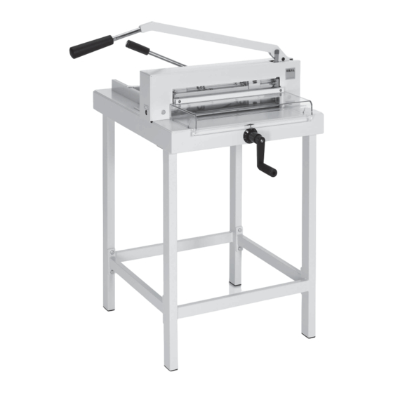
- Page 6 • • • Installation ا ﻟ ﺘ ﺮ ﻛ ﻴ Unpack the stand (accessory) and assemble according to the enclosed separate instructions. • • • . .( • Assembly of stand: 2 strong people are required to lift the machine out of the packaging. •...
- Page 7 • • • Installation ا ﻟ ﺘ ﺮ ﻛ ﻴ Screw on the backgauge crank, (F) the handle (J) and the clamping lever (D) found in the tool set (W). - 7 -...
- Page 8 • • • Operation ا ﻹ ﺳ ﺘ ﺨ ﺪ ا م Operating elements - Blade lever - Blade lock - Front safety guard - Paper clamp - Blade adjustment - Backgauge crank - Backgauge - Side lay left - Measurement indication - Handle for blade lever - Cover - Cutting stick...
- Page 9 • • • Operation ا ﻹ ﺳ ﺘ ﺨ ﺪ ا م • • • It is not allowed to operate the machine if the operating and safety instructions have not been understood. Please check the safety devices upon their function and completeness before working with.
- Page 10 • • • Operation ا ﻹ ﺳ ﺘ ﺨ ﺪ ا م ) .( 208.50 The measurement is set with the backgauge crank (F). Proceed to position from the rear. Measurement is indicated on the back side lay (H) (mm/inch). The fi...
- Page 11 • • • Operation ا ﻹ ﺳ ﺘ ﺨ ﺪ ا م Pull out the handle to avoid the measurement being wrongly adjusted. The blade lever (A) is locked in its top position. Lift the front guard (C) and place the pile of paper onto the machine making sure it is positioned exactly against the backgauge (G) and side lay (H) on the left.
- Page 12 • • • Operation ا ﻹ ﺳ ﺘ ﺨ ﺪ ا م Before every cut the lever (D) must be pushed to the left and tightened with light pressure. Bring down the front guard (C). Release the blade lock (B) and move the blade lever (A) down using both hands.
- Page 13 • • • Operation ا ﻹ ﺳ ﺘ ﺨ ﺪ ا م After cutting the paper move the blade lever (A) back to its top position until the blade lever is locked. Turn the lever to the right (D). Lift up the hand guard (C) and remove the paper from the machine.
- Page 14 • • • Blade and cutting stick replacement If the cutting quality decreases: • Check the cutting depth (see page 22). • Check the cutting stick (see page 16). • Replace or re-grind the blade (see page 14 - 23). The blade cannot be ground if the blade height is less than 83 mm / 3,29 inches.
- Page 15 • • • Blade and cutting stick replacement Changing the blade must be done from the front of the machine: Move the blade lever (A) up and secure it. Lift front guard (C) and remove 2 blade screws on the elongated holes (Q). (Found in the tool set).
- Page 16 • • • Blade and cutting stick replacement ) .(. Check the cutting stick: Lift the cutting stick by hand and pull it out.If needed the cutting stick can be turned or exchanged (2.). (The cutting stick can be used eight times). After exchanging the cutting stick close the clamp by moving the clamp lever to the left (3).
- Page 17 • • • Blade and cutting stick replacement . .( . .( Attach the blade changing tool (R) to the blade and screw tightly (1.). Remove the remaining blade screws (2.). Push the blade and blade changing tool (A) to the right and lower to remove (1.) Place the blade into the blade carrier (B) and screw it into place (2).
- Page 18 • • • Blade and cutting stick replacement • Take the exchange blade carefully out of the blade box and screw it to the blade changing tool (A) • blade must be covered! (B). Danger! Risk of injury! - 18 -...
- Page 19 • • • Blade and cutting stick replacement Place the blade to be exchanged, using the blade changing tool, into the blade carrier and push to the top and to the left.(1.) (see picture A) while doing so push both springs back.
- Page 20 • • • Blade and cutting stick replacement Push the blade changing tool to the top with your hand (1.). First, lightly tighten the middle blade screw with your other hand (2.) and then both blade screws left and right (3.). Remove the blade changing tool (R) (unscrew the grips).
- Page 21 • • • Blade and cutting stick replacement Lightly tighten the 2 blade screws on the elongated holes (1.). ) - ( Turn the knob for blade depth adjustment (E) completely to the right (-). - 21 -...
- Page 22 • • • Blade and cutting stick replacement • • E) (.3 Check the cutting depth: Open the clamp by moving the clamp lever to the right (1.). Remove all tools and place sheets of paper along the entire cutting length. •...
- Page 23 • • • Blade and cutting stick replacement Move the blade lever (A) up and secure it. Lift front guard (C) and tighten the 5 screws. - 23 -...
- Page 24 • • • Maintenance and cleaning Maintenance work may only be performed by trained staff. Nr. 9800 147 Nr. 9001 828 From time to time all movable parts have to be lubricated. (Use non-resinous grease). All paper and dust should be removed, as well as and grease.
- Page 25 • • • Maintenance and cleaning The blade lever (A) should never fall automatically. If necessary tighten the hexagon screw. Remove the cover (K), remove the two screws (P) on the cover (1.).Close the clamp (2.). Release the blade lock (3.) and move the blade lever slightly to the left (4.).
- Page 26 • • • Possible malfuntions Machine does not function! • • . .( Cut cannot be made. • Close the front cover (C) (1.) • Release the blade lock (2.) and pull down the hand lever (A) with both hands (3.). •...
- Page 27 Cutting quality decreases or cutting is very diffi cult to make. (Blade is blunt) • change the blade (see page 14 - 23). • www.ideal.de "Service" service@krug-priester.com Service None of the above mentioned methods helped to solve the problem: Contact Service team under •...
- Page 28 Accessories • • • Recommended Accessories: No. 9000 121 Blade No. 9000 121 No. 9000 221 Cutting stick (6 pieces) No. 9000 221 No. 9000 522 Blade changing tool No. 9000 522 No. 4205 1100 Stand No. 4205 1100 Included in delivery. - 28 -...
- Page 29 • BGI 721 2015 DIN EN ISO 9001:2008 DIN EN ISO 14001 4305 GS-IDENT. No. 11430501 This machine is approved by independent safety laboratories. The company is certifi ed under the DIN EN ISO 9001:2015 and DIN EN ISO 14001 quality standards.
- Page 30 Technical data • • • ةكرش ىدلKrug + Priester :ةيلاتلا تاداهشلا • قفو ةدوجلا ةرادإ ماظن DIN EN ISO 9001:2015 • قفو ةئيبلا ةرادإ ماظن DIN EN ISO 14001:2009 • قفو ةقاطلا ةرادإ ماظن DIN EN ISO 50001:2011 The company Krug + Priester has the following certifi...
- Page 31 Remarks: - 31 -...
- Page 32 IDEAL • Made in Germany • • Document Shredders • • • • Trimmers and Guillotines • • Krug & Priester GmbH & Co KG Simon-Schweitzer-Str. 34 D-72336 Balingen (Germany) www.krug-priester.com IDEAL 10-2015 31.01.2019 zm...
Need help?
Do you have a question about the 4305 and is the answer not in the manual?
Questions and answers