
Related Manuals for Comtrend Corporation NEXUSLINK 3111u


Summary of Contents for Comtrend Corporation NEXUSLINK 3111u
- Page 1 NEXUSLINK 3111u Multi-DSL Bonded Router User Manual Version C1.1, May 8, 2013 261113-00x PDF created with pdfFactory Pro trial version www.pdffactory.com...
- Page 2 Preface This manual provides information related to the installation and operation of this device. The individual reading this manual is presumed to have a basic understanding of telecommunications terminology and concepts. If you find the product to be inoperable or malfunctioning, please contact technical support for immediate service by email at INT-support@comtrend.com For product update, new product release, manual revision, or software upgrades,...
- Page 3 Copyright Copyright© 2013 Comtrend Corporation. All rights reserved. The information contained herein is proprietary to Comtrend Corporation. No part of this document may be translated, transcribed, reproduced, in any form, or by any means without the prior written consent of Comtrend Corporation.
- Page 4 Protect Our Environment This symbol indicates that when the equipment has reached the end of its useful life, it must be taken to a recycling centre and processed separate from domestic waste. The cardboard box, the plastic contained in the packaging, and the parts that make up this router can be recycled in accordance with regionally established regulations.
-
Page 5: Table Of Contents
Table of Contents CHAPTER 1 INTRODUCTION......................6 1.1 F ............................6 EATURES 1.2 A ...........................7 PPLICATION CHAPTER 2 INSTALLATION......................8 2.1 H ...........................8 ARDWARE ETUP 2.2 LED I ...........................10 NDICATORS CHAPTER 3 WEB USER INTERFACE....................12 3.1 D ........................12 EFAULT ETTINGS 3.2 IP C ........................12 ONFIGURATION 3.3 L... - Page 6 5.16 I .........................62 NTERFACE ROUPING 5.17 IP S ............................64 5.18 C ..........................67 ERTIFICATE 5.18.1 Local ..........................67 5.18.2 Trusted CA ........................70 5.19 M ..........................71 ULTICAST CHAPTER 6 WIRELESS ........................72 6.1 B ............................72 ASIC 6.2 S ............................74 ECURITY 6.2.1 WPS ............................76 6.3 MAC F ..........................81 ILTER 6.4 W...
-
Page 7: Chapter 1 Introduction
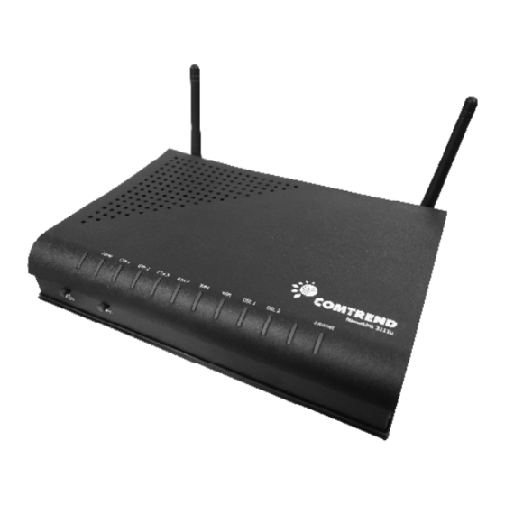
Chapter 1 Introduction The NEXUSLINK 3111u MULTI-DSL Bonded Router features flexible networking connectivity with dual DSL line capability, four 10/100 Ethernet ports, one Gigabit Ethernet port and one USB Host port. It has robust routing capabilities to segment and direct data streams and allows for multiple data encapsulations. -
Page 8: Application
1.2 Application The following diagrams depict typical applications of the NEXUSLINK 3111u. PDF created with pdfFactory Pro trial version www.pdffactory.com... -
Page 9: Chapter 2 Installation
Indicators for details). NOTE: If pressed down for more than 20 seconds, the NEXUSLINK 3111u will go into a firmware update state (CFE boot mode). The firmware can then be updated using an Internet browser pointed to the default IP address. - Page 10 Connect to an VDSL with this RJ11 Port. This device contains a micro filter which removes the analog phone signal. If you wish, you can connect a regular telephone to the same line by using a POTS splitter. FRONT PANEL The Wi-Fi &...
-
Page 11: Led Indicators
2.2 LED Indicators The front panel LED indicators are shown below and explained in the following table. This information can be used to check the status of the device and its connections. Color Mode Description Power on Green Power off POWER POST (Power On Self Test) failure (not bootable) or Device malfunction... - Page 12 DSL2 attempting sync: Flashing at 2 Hz with a 50% duty cycle when trying to detect carrier signal Blink Flashing at 4 Hz with a 50% duty cycle when the carrier has been detected and the modem is trying to train The wireless module is ready.
-
Page 13: Chapter 3 Web User Interface
Restore Default Configuration option in the Restore Settings screen. 3.2 IP Configuration DHCP MODE When the NEXUSLINK 3111u powers up, the onboard DHCP server will switch on. Basically, the DHCP server issues and reserves IP addresses for LAN devices, such as your PC. - Page 14 STEP 4: Click OK to submit these settings. If you experience difficulty with DHCP mode, you can try static IP mode instead. PDF created with pdfFactory Pro trial version www.pdffactory.com...
- Page 15 STATIC IP MODE In static IP mode, you assign IP settings to your PC manually. Follow these steps to configure your PC IP address to use subnet 192.168.1.10. NOTE: The following procedure assumes you are running Windows XP. However, the general steps involved are similar for most operating systems (OS).
-
Page 16: Login Procedure
3.3 Login Procedure Perform the following steps to login to the web user interface. NOTE: The default settings can be found in 3.1 Default Settings. STEP 1: Start the Internet browser and enter the default IP address for the device in the Web address field. - Page 17 STEP 3: After successfully logging in for the first time, you will reach this screen. PDF created with pdfFactory Pro trial version www.pdffactory.com...
-
Page 18: Chapter 4 Device Information
Chapter 4 Device Information The web user interface window is divided into two frames, the main menu (at left) and the display screen (on the right). The main menu has several options and selecting each of these options opens a submenu with more selections. NOTE: The menu items shown are based upon the configured connection(s) and user account privileges. -
Page 19: Wan
4.1 WAN Select WAN from the Device Info submenu to display the configured PVC(s). Heading Description Interface Name of the interface for WAN Description Name of the WAN connection Type Shows the connection type VlanMuxId Shows 802.1Q VLAN ID IPv6 Shows WAN IPv6 address IGMP Shows Internet Group Management Protocol (IGMP) status... -
Page 20: Statistics
4.2 Statistics This selection provides LAN, WAN, ATM/PTM and xDSL statistics. NOTE: These screens are updated automatically every 15 seconds. Click Reset Statistics to perform a manual update. 4.2.1 LAN Statistics This screen shows data traffic statistics for each LAN interface. Heading Description Interface... -
Page 21: Wan Statistics
4.2.2 WAN Statistics This screen shows data traffic statistics for each WAN interface. Heading Description Interface WAN interfaces Description WAN service label Received/Transmitted - Bytes Number of Bytes - Pkts Number of Packets - Errs Number of packets with errors - Drops Number of dropped packets PDF created with pdfFactory Pro trial version... -
Page 22: Atm Statistics
4.2.3 ATM Statistics The following figure shows Asynchronous Transfer Mode (ATM) statistics. XTM Interface Statistics Heading Description Port Number ATM PORT (0-3) In Octets Number of received octets over the interface Out Octets Number of transmitted octets over the interface In Packets Number of packets received over the interface Out Packets... -
Page 23: Xdsl Statistics
4.2.4 xDSL Statistics The xDSL Statistics screen displays information corresponding to the xDSL type. The two examples below (VDSL) show this variation. VDSL Click the Reset Statistics button to refresh this screen. PDF created with pdfFactory Pro trial version www.pdffactory.com... - Page 24 Field Description Mode VDSL, MULTI-DSL Traffic Type ATM, PTM Status Lists the status of the DSL link Link Power State Link output power state. Line Coding (Trellis) Trellis On/Off SNR Margin (0.1 dB) Signal to Noise Ratio (SNR) margin Attenuation (0.1 dB) Estimate of average loop attenuation in the downstream direction.
- Page 25 Total ES Total Number of Errored Seconds Total SES Total Number of Severely Errored Seconds Total UAS Total Number of Unavailable Seconds xDSL BER TEST Click xDSL BER Test on the xDSL Statistics screen to test the Bit Error Rate (BER). A small pop-up window will open after the button is pressed, as shown below.
-
Page 26: Route
4.3 Route Choose Route to display the routes that the NEXUSLINK 3111u has found. Field Description Destination Destination network or destination host Gateway Next hub IP address Subnet Mask Subnet Mask of Destination Flag U: route is up !: reject route... -
Page 27: Arp
4.4 ARP Click ARP to display the ARP information. Field Description IP address Shows IP address of host pc Flags Complete, Incomplete, Permanent, or Publish HW Address Shows the MAC address of host pc Device Shows the connection interface PDF created with pdfFactory Pro trial version www.pdffactory.com... -
Page 28: Dhcp
4.5 DHCP Click DHCP to display all DHCP Leases. Field Description Hostname Shows the device/host/PC network name MAC Address Shows the Ethernet MAC address of the device/host/PC IP Address Shows IP address of device/host/PC Expires In Shows how much time is left for each DHCP Lease PDF created with pdfFactory Pro trial version www.pdffactory.com... -
Page 29: Chapter 5 Advanced Setup
Chapter 5 Advanced Setup 5.1 Layer 2 Interface The ATM, PTM and ETH WAN interface screens are described here. 5.1.1 ATM Interface Add or remove ATM interface connections here. Click Add to create a new ATM interface (see Appendix NOTE: Up to 8 ATM interfaces can be created and saved in flash memory. -
Page 30: Ptm Interface
5.1.2 PTM Interface Add or remove PTM interface connections here. Click Add to create a new connection (see Appendix G - Connection Setup). To remove a connection, select its Remove column radio button and click Remove. 5.1.3 ETH INTERFACE This screen displays the Ethernet WAN Interface configuration. NOTE: This option only applies to models with an Ethernet WAN port. -
Page 31: Wan Service
5.2 WAN Service This screen allows for the configuration of WAN interfaces. Click the Add button to create a new connection. For connections on ATM or ETH WAN interfaces see Appendix G - Connection Setup. NOTE: ETH and ATM service connections cannot coexist. In Default Mode, up to 8 WAN connections can be configured;... -
Page 32: Lan
5.3 LAN Configure the LAN interface settings and then click Apply/Save. Consult the field descriptions below for more details. GroupName: Select an Interface Group. LAN INTERFACE IP Address: Enter the IP address for the LAN port. Subnet Mask: Enter the subnet mask for the LAN port. Enable IGMP Snooping: Enable by ticking the checkbox þ. - Page 33 Enable LAN side firewall: Enable by ticking the checkbox þ. DHCP Server: To enable DHCP, select Enable DHCP server and enter Start and End IP addresses and the Leased Time. This setting configures the router to automatically assign IP, default gateway and DNS server addresses to every PC on your LAN.
-
Page 34: Ipv6 Lan Auto Configuration
5.4 IPv6 LAN Auto Configuration Configure the IPv6 LAN Host options (see below) and then click Save/Apply. DHCPv6 Server: To enable DHCP for IPv6, select the Enable DHCPv6 server checkbox þ. This setting enables the router to assign IP settings to every IPv6-capable LAN device (IPv6 clients). -
Page 35: Nat
5.5 NAT To display this option, NAT must be enabled in at least one PVC shown on the Chapter 5 Advanced Setup. 5.5.1 Virtual Servers Virtual Servers allow you to direct incoming traffic from the WAN side (identified by Protocol and External port) to the Internal server with private IP addresses on the LAN side. -
Page 36: Port Triggering
Field/Header Description Use Interface Select a WAN interface from the drop-down box. Select a Service User should select the service from the list. Custom Service User can enter the name of their choice. Server IP Address Enter the IP address for the server. External Port Start Enter the starting external port number (when you select Custom Server). - Page 37 Consult the table below for field and header descriptions. Field/Header Description Use Interface Select a WAN interface from the drop-down box. Select an Application User should select the application from the list. Custom Application User can enter the name of their choice. Trigger Port Start Enter the starting trigger port number (when you select custom application).
-
Page 38: Dmz Host
5.5.3 DMZ Host The DSL router will forward IP packets from the WAN that do not belong to any of the applications configured in the Virtual Servers table to the DMZ host computer. To Activate the DMZ host, enter the DMZ host IP address and click Save/Apply. To Deactivate the DMZ host, clear the IP address field and click Save/Apply. -
Page 39: Security
5.6 Security To display this function, you must enable the firewall feature in WAN Setup. For detailed descriptions, with examples, please consult Appendix A - Firewall. 5.6.1 IP Filtering This screen sets filter rules that limit IP traffic (Outgoing/Incoming). Multiple filter rules can be set and each applies at least one limiting condition. - Page 40 Field Description Filter Name The filter rule label. IP Version Select from the drop down menu. Protocol TCP, TCP/UDP, UDP, or ICMP. Source IP address Input source IP address. Source Port (port or port:port) Input source port number or range. Destination IP address Input destination IP address.
- Page 41 Field Description Filter Name The filter rule label IP Version Select from the drop down menu. Protocol TCP, TCP/UDP, UDP, or ICMP. Source IP address Enter source IP address. Source Port (port or port:port) Enter source port number or range. Destination IP address Enter destination IP address.
-
Page 42: Mac Filtering
Each network device has a unique 48-bit MAC address. This can be used to filter (block or forward) packets based on the originating device. MAC filtering policy and rules for the NEXUSLINK 3111u can be set according to the following procedure. The MAC Filtering Global Policy is defined as follows. FORWARDED means that all MAC layer frames will be FORWARDED except those matching the MAC filter rules. -
Page 43: Parental Control
Consult the table below for detailed field descriptions. Field Description Protocol Type PPPoE, IPv4, IPv6, AppleTalk, IPX, NetBEUI, IGMP Destination MAC Address Defines the destination MAC address Source MAC Address Defines the source MAC address Frame Direction Select the incoming/outgoing packet interface WAN Interfaces Applies the filter to the selected bridge interface. -
Page 44: Url Filter
See below for field descriptions. Click Apply/Save to add a time restriction. User Name: A user-defined label for this restriction. Browser's MAC Address: MAC address of the PC running the browser. Other MAC Address: MAC address of another LAN device. Days of the Week: The days the restrictions apply. - Page 45 Enter the URL address and port number then click Save/Apply to add the entry to the URL filter. URL Addresses begin with “www”, as shown in this example. A maximum of 100 entries can be added to the URL Filter list. Tick the Exclude radio button to deny access to the websites listed.
-
Page 46: Quality Of Service (Qos)
5.8 Quality of Service (QoS) NOTE: QoS must be enabled in at least one PVC to display this option. (see Appendix G - Connection Setup for detailed PVC setup instructions). 5.8.1 Queue Management Configuration To Enable QoS tick the checkbox þ and select a Default DSCP Mark. Click Apply/Save to activate QoS. -
Page 47: Queue Configuration
5.8.2 Queue Configuration This function follows the Differentiated Services rule of IP QoS. You can create a new Queue entry by clicking the Add button. Enable and assign an interface and precedence on the next screen. Click Save/Reboot on this screen to activate it. Click Enable to activate the QoS Queue. -
Page 48: Qos Classification
5.8.3 QoS Classification The network traffic classes are listed in the following table. Click Add to configure a network traffic class rule and Enable to activate it. To delete an entry from the list, click Remove. This screen creates a traffic class rule to classify the upstream traffic, assign queuing priority and optionally overwrite the IP header DSCP byte. - Page 49 Field Description Traffic Class Name Enter a name for the traffic class. Rule Order Last is the only option. Rule Status Disable or enable the rule. Classification Criteria Class Interface Select an interface (i.e. Local, eth0-4, wl0) Ether Type Set the Ethernet type (e.g. IP, ARP, IPv6). Source MAC Address A packet belongs to SET-1, if a binary-AND of its source MAC address with the Source MAC Mask is equal to the...
-
Page 50: Routing
5.9 Routing These following routing functions are accessed from this menu: Default Gateway, Static Route, Policy Routing, RIP and IPv6 Static Route. NOTE: In bridge mode, the RIP menu option is hidden while the other menu options are shown but ineffective. 5.9.1 Default Gateway Default gateway interface list can have multiple WAN interfaces served as system... -
Page 51: Static Route
5.9.2 Static Route This option allows for the configuration of static routes by destination IP. Click Add to create a static route or click Remove to delete a static route. After clicking Add the following screen will display. Select the IP Version from the drop down menu. Input the Destination IP Address, select the interface and input the Gateway IP Address. -
Page 52: Policy Routing
5.9.3 Policy Routing This option allows for the configuration of static routes by policy. Click Add to create a routing policy or Remove to delete one. On the following screen, complete the form and click Save/Apply to create a policy. PDF created with pdfFactory Pro trial version www.pdffactory.com... -
Page 53: Rip
5.9.4 To activate RIP, configure the RIP version/operation mode and select the Enabled checkbox þ for at least one WAN interface before clicking Save/Apply. PDF created with pdfFactory Pro trial version www.pdffactory.com... -
Page 54: Dns
5.10 DNS 5.10.1 DNS Server Select DNS Server Interface from available WAN interfaces OR enter static DNS server IP addresses for the system. In ATM mode, if only a single PVC with IPoA or static IPoE protocol is configured, Static DNS server IP addresses must be entered. Click Apply/Save to save the new configuration. -
Page 55: Dynamic Dns
5.10.2 Dynamic DNS The Dynamic DNS service allows you to map a dynamic IP address to a static hostname in any of many domains, allowing the NEXUSLINK 3111u to be more easily accessed from various locations on the Internet. To add a dynamic DNS service, click Add. The following screen will display. - Page 56 Field Description D-DNS provider Select a dynamic DNS provider from the list Hostname Enter the name of the dynamic DNS server Interface Select the interface from the list Username Enter the username of the dynamic DNS server Password Enter the password of the dynamic DNS server PDF created with pdfFactory Pro trial version www.pdffactory.com...
-
Page 57: Dsl
5.11 DSL The DSL Settings screen allows for the selection of DSL modulation modes. For optimum performance, the modes selected should match those of your ISP. DSL Mode Data Transmission Rate - Mbps (Megabits per second) G.Dmt Downstream: 12 Mbps Upstream: 1.3 Mbps G.lite Downstream:... - Page 58 Advanced DSL Settings Click Advanced Settings to reveal additional options. On the following screen you can select a test mode or modify tones by clicking Tone Selection. Click Apply to implement these settings and return to the previous screen. On this screen you select the tones you want activated, then click Apply and Close. PDF created with pdfFactory Pro trial version www.pdffactory.com...
-
Page 59: Dsl Bonding
5.12 DSL Bonding This page allows you to enable / disable DSL Bonding. NOTE: This configuration doesn't take effect until router is rebooted. PDF created with pdfFactory Pro trial version www.pdffactory.com... -
Page 60: Upnp
5.13 UPnP Select the checkbox þ provided and click Apply/Save to enable UPnP protocol. PDF created with pdfFactory Pro trial version www.pdffactory.com... -
Page 61: Dns Proxy
5.14 DNS Proxy DNS proxy receives DNS queries and forwards DNS queries to the Internet. After the CPE gets answers from the DNS server, it replies to the LAN clients. Configure DNS proxy with the default setting, when the PC gets an IP via DHCP, the domain name, Home, will be added to PC’s DNS Suffix Search List, and the PC can access route with “Comtrend.Home”. -
Page 62: Print Server
5.15 Print Server The NEXUSLINK 3111u can provide printer support through an optional USB2.0 host port. If your device has this port, refer to Appendix F - Printer Server for detailed setup instructions. PDF created with pdfFactory Pro trial version... -
Page 63: Interface Grouping
5.16 Interface Grouping Interface Grouping supports multiple ports to PVC and bridging groups. Each group performs as an independent network. To use this feature, you must create mapping groups with appropriate LAN and WAN interfaces using the Add button. The Remove button removes mapping groups, returning the ungrouped interfaces to the Default group. - Page 64 Automatically Add Clients With Following DHCP Vendor IDs: Add support to automatically map LAN interfaces to PVC's using DHCP vendor ID (option 60). The local DHCP server will decline and send the requests to a remote DHCP server by mapping the appropriate LAN interface. This will be turned on when Interface Grouping is enabled.
-
Page 65: Ip Sec
If a set-top box is connected to ENET1 and sends a DHCP request with vendor ID "Video", the local DHCP server will forward this request to the remote DHCP server. The Interface Grouping configuration will automatically change to the following: 1. - Page 66 IPSec Connection Name User-defined label Remote IPSec Gateway Address The location of the Remote IPSec Gateway. IP address or domain name can be used. Tunnel access from local IP Specify the acceptable host IP on the local addresses side. Choose Single or Subnet. IP Address/Subnet Mask for VPN If you chose Single, please enter the host IP address for VPN.
- Page 67 Advanced IKE Settings Select Show Advanced Settings to reveal the advanced settings options shown below. Advanced IKE Settings Select Hide Advanced Settings to hide the advanced settings options shown above. Phase 1 / Phase 2 Choose settings for each phase, the available options are separated with a “/”...
-
Page 68: Certificate
5.18 Certificate A certificate is a public key, attached with its owner’s information (company name, server name, personal real name, contact e-mail, postal address, etc) and digital signatures. There will be one or more digital signatures attached to the certificate, indicating that these entities have verified that this certificate is valid. - Page 69 The following table is provided for your reference. Field Description Certificate Name A user-defined name for the certificate. Common Name Usually, the fully qualified domain name for the machine. Organization Name The exact legal name of your organization. Do not abbreviate. State/Province Name The state or province where your organization is located.
- Page 70 IMPORT CERTIFICATE Click Import Certificate to paste the certificate content and the private key provided by your vendor/ISP/ITSP into the corresponding boxes shown below. Input a certificate name and click Apply to import the local certificate. PDF created with pdfFactory Pro trial version www.pdffactory.com...
-
Page 71: Trusted Ca
5.18.2 Trusted CA CA is an abbreviation for Certificate Authority, which is a part of the X.509 system. It is itself a certificate, attached with the owner information of this certificate authority; but its purpose is not encryption/decryption. Its purpose is to sign and issue certificates, in order to prove that these certificates are valid. -
Page 72: Multicast
5.19 Multicast Input new IGMP protocol configuration fields if you want modify default values shown. Then click Apply/Save. PDF created with pdfFactory Pro trial version www.pdffactory.com... -
Page 73: Chapter 6 Wireless
Chapter 6 Wireless The Wireless menu provides access to the wireless options discussed below. 6.1 Basic The Basic option allows you to configure basic features of the wireless LAN interface. Among other things, you can enable or disable the wireless LAN interface, hide the network from active scans, set the wireless network name (also known as SSID) and restrict the channel set based on country requirements. - Page 74 Option Description Disable WMM Stops the router from ‘advertising’ its Wireless Multimedia (WMM) Advertise functionality, which provides basic quality of service for time-sensitive applications (e.g. VoIP, Video). Enable Select the checkbox þ to enable this function. Wireless Multicast Forwarding SSID Sets the wireless network name.
-
Page 75: Ecurity
6.2 Security The following screen appears when Wireless Security is selected. The options shown here allow you to configure security features of the wireless LAN interface. Click Save/Apply to implement new configuration settings. WIRELESS SECURITY Wireless security settings can be configured according to Wi-Fi Protected Setup (WPS) or Manual Setup. - Page 76 The settings for WPA authentication are shown below. The settings for WPA-PSK authentication are shown next. PDF created with pdfFactory Pro trial version www.pdffactory.com...
-
Page 77: Wps
Every WPS certified device has both a PIN number and a push button, located on the device or accessed through device software. The NEXUSLINK 3111u has both a WPS button on the device and a virtual button accessible from the web user interface (WUI). - Page 78 NEXUSLINK 3111u. NOTES: Your client may or may not have the ability to provide security settings to the NEXUSLINK 3111u. If it does not, then you must set the WSC AP mode to Configured. Consult the device documentation to check its capabilities.
- Page 79 Step 5: Click the Save/Apply button at the bottom of the screen. IIIa. PUSH-BUTTON CONFIGURATION The WPS push-button configuration provides a semi-automated configuration method. The WPS button on the rear panel of the router can be used for this purpose or the Web User Interface (WUI) can be used exclusively. The WPS push-button configuration is described in the procedure below.
-
Page 80: Software
IIIb. WPS – PIN CONFIGURATION Using this method, security settings are configured with a personal identification number (PIN). The PIN can be found on the device itself or within the software. The PIN may be generated randomly in the latter case. To obtain a PIN number for your client, check the device documentation for specific instructions. - Page 81 The example below shows that the connection established successfully. You can also double-click the Wireless Network Connection icon from the Network Connections window (or the system tray) to confirm the status of the new connection. PDF created with pdfFactory Pro trial version www.pdffactory.com...
Need help?
Do you have a question about the NEXUSLINK 3111u and is the answer not in the manual?
Questions and answers