Table of Contents
Advertisement
Quick Links
Advertisement
Table of Contents

Subscribe to Our Youtube Channel
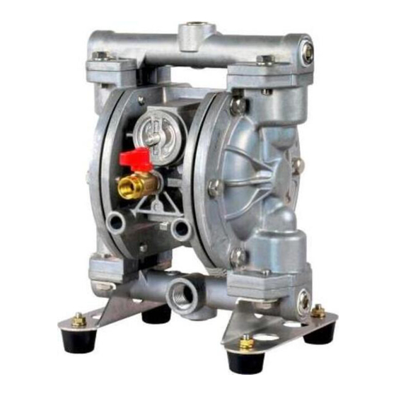
Summary of Contents for YAMADA Global Series
- Page 1 Doc. No. NDP 497M-02 MAINTENANCE MANUAL G15 Series...
-
Page 2: Warnings And Cautions
After reading this document, be sure to keep it handy for future reference. These maintenance manuals cover what you should know about maintenance of the Yamada G15 Series Diaphragm Pumps. This edition is based on the standards for the August 2018 production run. Remember, the specifications are always subject to change;... -
Page 3: Table Of Contents
Table of Contents ·Warnings and Cautions ·Table of Contents 1.Principles of operation ··························································· 1 2.Tools, etc. 2.1 General tools ······································································· 1 2.2 Special tools ········································································ 1 2.3 Misc. ·················································································· 1 3.Ordering Replacement parts ··················································· 1 4.Balls, Valve seats 4.1 Removal ············································································· 2 4.2 Inspection ···········································································... -
Page 4: Principles Of Operation
1. Principles of operation There are two diaphragms fixed to the center rod, one at each end. When compressed air is supplied to air chamber b (right side, see Fig.1.1), the center rod moves to the right, the material in material chamber B is pushed out, and at the same time material is sucked into material chamber A. -
Page 5: Balls, Valve Seats
4. Balls, Valve seats 4.1 Removal ■A_, S_ Type ▪ Remove 4 mounting bolts from upper manifold and remove the manifold. [Fig.4.1] Fig.4.1 ▪ Remove the O ring, valve stopper, ball, valve seat. [Fig.4.2] Fig.4.2 ▪ Turn over the main body assembly. [Fig.4.3] ▪... - Page 6 ■P_ Type ▪ Remove 4 mounting bolts from upper manifold A and remove the manifold A. [Fig.4.5] Fig.4.5 ▪ Remove the Ball, valve seat A, valve seat B, O ring. [Fig.4.6] Fig.4.6 ▪ Turn over the main body assembly. [Fig.4.7] ▪...
-
Page 7: Inspection
4.2 Inspection ▪ Ball [Fig.4.9] Measure the outside diameter, and if it is outside the usable range, replace the ball. Usable range of Ball Sø0.669 ~ Sø0.760 in {Sø17.0 ~ Sø19.3 mm} ▪ O ring Fig.4.9 If O ring is worn out or cracked, replace it. Replace the PTFE O ring regardless of its condition. -
Page 8: Diaphragm And Center Rod
5. Diaphragm and Center rod 5.1 Removal ■A_, S_ Type ▪ Remove the O ring, valve stopper, ball, valve seat (see [4.1 Removal]). ▪ Remove the 12 retainer bolts from the out chamber, and remove the out chamber. [Fig.5.1] Fig.5.1 ▪... - Page 9 ■P_ Type ▪ Remove the ball, valve seat A, valve seat B, O ring. (see [4.1 Removal]). ▪ Remove the 16 retainer bolts from the out chamber, and remove the out chamber. [Fig.5.5] Fig.5.5 ▪ Remove the center disk on both sides of the center rod. [Fig.5.6] ▪...
-
Page 10: Inspection
5.2 Inspection ▪ Diaphragm If the diaphragm is worn out or damaged, replace it. New replace just one diaphragm. Guideline of diaphragm life NBR, PTFE 10,000,000 cycle A_, S_ 15,000,000 cycle PTFE 7,000,000 cycle (Including backup diaphragm) 10,000,000 cycle ▪ Center rod [Fig.5.8] Measure the diameter, and if it is outside the usable range, replace the center rod. -
Page 11: Guide Bush
■P_ Type ▪ Apply grease to the center rod, and insert it into the main body. ▪ PT type (PTFE Diaphragm model): Put the backup diaphragm before PTFE diaphragm, and O ring after PTFE diaphragm. (cf. Fig.5.11) ▪ Keep the convex side to the outside for diaphragm and backup diaphragm. -
Page 12: Inspection
6.2 Inspection ▪ O ring If the O ring is worn out or cracked, replace it. ■A_, S_ Type ▪ Guide bush [Fig.6.3] Measure the inside diameter, and if it is outside the usable range, replace the guide. Usable range of guide ø0.6299 ~ ø0.6378 in {ø16.0 ~ø16.2 mm} Fig.6.3 ■P_ Type... -
Page 13: Spool Assembly And Sleeve
7. Spool assembly and Sleeve 7.1 Removal ■A_, S_ Type ▪ Loosen the plug with hexagonal box wrench and remove remaining air from inside the pump. [Fig.7.1] Fig.7.1 ▪ Remove the cap A and cap B using the cap and disk remover. (special tool: Part No. - Page 14 ■P_ Type ▪ Remove 4 nuts fixing the valve body assembly and draw out the valve body assembly from the main body. [Fig.7.5] Fig.7.5 ▪ Remove the cap using the Pliers. [Fig.7.6] Fig.7.6 ▪ Remove the cushion, and then push out the spool assembly from opposite side.
-
Page 15: Inspection
7.2 Inspection ▪ Spool assembly Seal ring [Fig.7.9] Close the diagonal slit and measure the outside diameter, and if it is outside the usable range, replace the spool assembly. If the Seal ring is worn out or cracked, replace spool assembly. -
Page 16: Retightening Of Tie Rods
8. Retightening of Tie rods ▪ The torque should be applied on the occasion of A_, S_ Type (1) Right before the pump to use. (2) There are any leaks of material on daily inspecting a pump. Retain bolts for the Retain bolts for the out chamber manifold... - Page 18 YAMADA AMERICA, INC 955 E. ALGONQUIN RD., ARLINGTON HEIGHTS, IL 60005, USA PHONE: 1-847-631-9200 or 1-800-990-7867 (Toll Free) FAX : 1-847-631-9273 www.yamadapump.com Manufactured by: YAMADA CORPORATION International Department 1-1-3 CHOME, MINAMI MAGOME, OHTA-KU, TOKYO, 143-8504, JAPAN PHONE : +81-(0)3-3777-0241 FAX : +81-(0)3-3777-0584...


Need help?
Do you have a question about the Global Series and is the answer not in the manual?
Questions and answers