Sign In
Upload
Download
Table of Contents
Contents
Add to my manuals
Delete from my manuals
Share
URL of this page:
HTML Link:
Bookmark this page
Add
Manual will be automatically added to "My Manuals"
Print this page
×
Bookmark added
×
Added to my manuals
Manuals
Brands
POP UP Manuals
Scissor Lifts
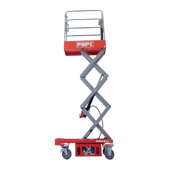
PUSH 6 PRO
Operator's safety and maintenance handbook
POP UP PUSH 6 PRO Operator's Safety And Maintenance Handbook
Hide thumbs
1
Table Of Contents
2
3
4
5
6
7
8
9
10
11
12
13
14
15
16
17
18
19
20
page
of
20
Go
/
20
Contents
Table of Contents
Bookmarks
Table of Contents
Table of Contents
Declaration of Conformity
Safety Rules
Introduction
Component Identification
Special Limitations
Platform Capacity
Manual Force
Lift Level Sensor Interlock
Lowering Alarm
Lowering Interrupt
Controls and Indicators
Lower Controls
Emergency Stop Button
Control Selector Switch
Ground Operation Button
Platform Raise/Lower Buttons
Battery Charger Mode Selector
Upper Controls
Emergency Stop Button
Interlock Button
Pre-Operation Safety Inspection
System Function Inspection
Operation
Preparing for Operation
Lower Controls
Upper Controls
Platform
Raising and Lowering
Lowering Interrupt
Component Tray
Emergency Lowering
Transporting the Machine
Preparing for Transportation
Transporting
Lifting with a Forklift
Lifting with a Tail Lift
Maintenance
Hydraulic Fluid
Check Hydraulic Fluid
Battery Maintenance
Battery Charging
Inspection and Maintenance Schedule
Daily Preventative Maintenance Checklist
Preventative Maintenance Report
General Specifications - Push 8 Pro
General Specifications - Push 6 Pro
General Specifications - Push 10 Pro
Advertisement
Quick Links
1
Platform Capacity
2
Battery Maintenance
3
General Specifications - Push 8 Pro
4
General Specifications - Push 6 Pro
5
General Specifications - Push 10 Pro
Download this manual
PUSH
F O R P U S H 6 P R O , P U S H 8 P R O
A N D P U S H 1 0 P R O
+44 (0)1244 833 933
O P E R ATO R ' S S A F E T Y A N D
M A I N T E N A N C E H A N D B OO K
F O R P U S H 6 P R O , P U S H 8 P R O & P U S H 1 0 P R O
PRO
info@popupproducts.co.uk
popupproducts.co.uk
Table of
Contents
Previous
Page
Next
Page
1
2
3
4
5
Advertisement
Table of Contents
Need help?
Do you have a question about the PUSH 6 PRO and is the answer not in the manual?
Ask a question
Questions and answers
Related Manuals for POP UP PUSH 6 PRO
Scissor Lifts POP UP PUSH 8 PRO Operator's Safety And Maintenance Handbook
(20 pages)
Scissor Lifts POP UP PUSH 10 PRO Operator's Safety And Maintenance Handbook
(20 pages)
Scissor Lifts POP UP IQ LIFT PRO10 Maintenance & Troubleshooting Handbook
(36 pages)
Scissor Lifts POP UP IQ LIFT PRO 10 Operations & Safety Handbook
Push-around mobile elevating work platform (32 pages)
Scissor Lifts POP UP PUSH 6 ECO Operator's Safety And Maintenance Handbook
(24 pages)
Scissor Lifts POP UP PRO 6 IQ Operator's Safety And Maintenance Handbook
(24 pages)
Scissor Lifts POP UP PRO 8 IQ Operator's Safety And Maintenance Handbook
(24 pages)
Scissor Lifts POP UP PRO 10 IQ Operator's Safety And Maintenance Handbook
(24 pages)
Scissor Lifts POP UP EIGER 250 Assembly Manual
Double & single width 3t (17 pages)
Scissor Lifts POP UP EIGER 500 Instruction Manual
Double & single width 3t (17 pages)
Scissor Lifts POP UP MiPOD 1000 Assembly Manual
(7 pages)
This manual is also suitable for:
Push 8 pro
Push 10 pro
Table of Contents
Print
Rename the bookmark
Delete bookmark?
Delete from my manuals?
Login
Sign In
OR
Sign in with Facebook
Sign in with Google
Upload manual
Upload from disk
Upload from URL


Need help?
Do you have a question about the PUSH 6 PRO and is the answer not in the manual?
Questions and answers