
Related Manuals for Genvex ECO 375 TS


Summary of Contents for Genvex ECO 375 TS
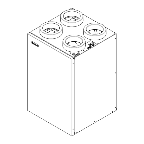
- Page 1 INSTALLATION MANUAL ECO 375 TS/TL Mechanical ventilation with passive heat recovery...
-
Page 2: Table Of Contents
TABLE OF CONTENT Installation ....................................3 Wall mounting (vertical) .............................4 Duct connection ................................5 Condensate drain .................................5 Duct system ...................................6 Insulation of ducts in cold loft spaces ........................6 Insulation of ducts in heated spaces ........................7 Reheating of the supply air ............................7 Electrical installation..............................8 Inspection and initial adjustment of appliance ....................8 Optimum initial adjustment of plant ........................8 Maintenance of ventilation unit ..........................9... -
Page 3: Installation
2) Install an air tight water trap on a non-freezing location to compensate for the fan pressure. ECO 375 TS/TL is supplied in a vertical version (as shown 3) The height of the water trap must be at least 50 mm. -
Page 4: Wall Mounting (Vertical)
IMPORTANT: The ECO375 ventilation unit can only be installed vertically. ECO 375 TS/TL is supplied with an universal wall mounting kit. Before starting the installation of the ventilation unit. Please ensure that the wall beeing used for holding the ventilation unit is built capable of holding the weight of the ventilation unit. -
Page 5: Duct Connection
Optimal operation is achieved by mounting a connector piece Ø160 mm with double sealing lips mm in each outlet of the ECO 375 TS/TL. Condensate drain The units produce up to 6 litres of condensate per day. It is... -
Page 6: Duct System
Insulation of ducts in cold loft spaces In order to exploit the unit’s high recovery potential (efficiency), it is necessary to insulate the ducts correctly. Genvex recommends as follows: Supply and extract ducts To minimise heat losses from the duct system in cold loft spaces, the supply and extract ducts must be insulated with a minimum of 100 mm insulation. -
Page 7: Insulation Of Ducts In Heated Spaces
Insulation of ducts in heated spaces Reheating of supply air Genvex recommends as follows: As the counter current heat exchanger cannot extract all the heat from the extract air and supply it to the supply Supply and extract ducts air, the supply air will be about 1-4°C colder than the room In warm loft spaces the supply and extract channels must temperature in the dwelling for the whole winter season. -
Page 8: Electrical Installation
To start up the unit before adjustment, do as follows: Before starting up the unit: 1: Check that the Genvex unit is correctly mounted and that all ducts are insulated as required. 2: Check that hatches can be opened so that service and maintenance on the unit can be carried out. -
Page 9: Maintenance Of Ventilation Unit
Maintenance of ventilation unit Turn off the electricity for the unit before opening it. Filters When the filter timer reaches the set value for filter G4 = Standard filter (coarse filter class G4) change, “Alarm!” will show in the screen saver and ”Chg. filter” will flash. This means that it is time to clean/ F7 = Pollen filter (fine filter class F7) change the filters. - Page 10 Condensate drain When changing the filter in August/September, before outside temperatures falls to 5°C, check the condensate drain for blockage by dirt and check that there is water in the water trap. Pour 1 litre water into the condensate tray and make sure it can run off without problems.
-
Page 11: Spare Parts
SPARE PARTS kation: G4 069222 069218 F7 069224 069231 M5 069223 G4 069222 069235 069219 069209 Optima 251 042478 Optima 260 042479 060535 TL 069285 TS 069282 069214 069237 069178 ALU 069210 PET 069211 069252 Item Description Item Description 069209 Bypass damper 069211 Heatexchanger PET (Plastic) -
Page 12: Troubleshooting
After the guarantee period (2 years ->) The installer from whom you have bought the system or Does not apply to PTC electrical heaters. the Genvex service department (+45 7353 2765). The system is not running Before calling, please write down the data from the inscription plate (silver plate on the unit). -
Page 13: Electrical Diagram - Opt251
ELECTRICAL DIAGRAM – OPT251 Q3= 0.5A Q4= 0.5A ES960C Q1= H8,H16,H17 Q2= H6,H7,H9 Q3= L1-L17 Q4= L1-L17 A = LED Flash - Power on B = LED Flash - Communication to Optima Display Q = Fuse L1 = Potential free input for optional: H1 = Mains connection 230 VAC Humidistat, Extractor hood ,CO2 H2 = (R2) Electric Reheater 230VAC... - Page 14 Potential free input for optional: Humidistat, Extractor hood , Optima Design +10V Mains connection 1x230VAC, L-N-PE Max: 13A Sensor, supply air Electric Reheater Sensor, fresh air H2 and H3 Max.load total Sensor, exhaust air 1800W Sensor, extract air Electric Preheater 0-10V White Signal...
-
Page 15: Electrical Diagram - Opt260
ELECTRICAL DIAGRAM – OPT260 Q3= 0,5A Q4= 0,5A Q1= H8,H14,H16,H17 Q2= H6,H7,H9 Q3= L1-L17 Q4= L1-L17 ES960CC A = LED Flash - Power on B = LED Flash - Startup D = LED Flash - Loads the program from sd card Q = Fuse L1 = Potential free input for optional: H1 = Mains connection 230 VAC... - Page 16 Potential free input for optional: Humidistat, Extractor hood , Sensor, supply air Mains connection 1x230VAC, L-N-PE Max: 13A Sensor, fresh air Sensor, exhaust air Electric Reheater Sensor, extract air H2 and H3 0-10V Max.load total 1800W White Signal Demand CTRL B1 Red/Brown Electric Preheater Blue/Green...
- Page 17 OPT 100/OPUS DISPLAY Connection for OPT 100 / OPUS control panel Speed button Reheat / Filter reset button Option 1 LED Speed 1 LED Speed 2 LED Speed 3 LED Speed 4 LED Reheat / Filter alarm Connection for boost button and filter reset button Boost button Filter reset button Option 2...
-
Page 18: Declaration Of Conformity
DECLARATION OF CONFORMITY Declaration of conformity can be downloaded at www.genvex.com. -
Page 19: Disassembly Instructions
DISASSEMBLY INSTRUCTIONS Remove filters Remove counterflow heat exchanger Remove fan Remove bypass actuator... - Page 20 – in fact you can recover up to 95% of the heat energy with a Genvex system. Please visit www.genvex.com to see a list of our distributors KVM-Genvex A/S • Sverigesvej 6 • DK-6100 Haderslev • Tel.: +45 73 53 27 00 • salgogsupport@genvex.dk • www.genvex.com...
Need help?
Do you have a question about the ECO 375 TS and is the answer not in the manual?
Questions and answers