Table of Contents
Advertisement
Advertisement
Table of Contents

Related Manuals for Carl Valentin ILX Series


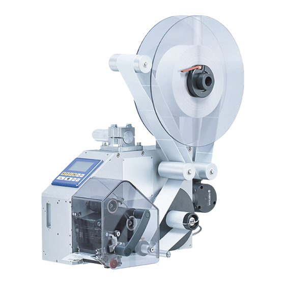
Summary of Contents for Carl Valentin ILX Series
- Page 2 It must not be concluded from the missing labelling that it is not a registered brand or a registered trademark. Carl Valentin printing systems comply with the following safety guidelines: EG Low-Voltage Directive (2006/95/EC)
-
Page 3: Table Of Contents
Table of Contents Table of Contents Table of Contents ................3 Introduction ................5 General Instructions ..............5 Intended Use ................5 Product Description ..............6 Safety Instructions ..............7 Operating Conditions ............... 9 Technical data ..............13 ILX 56/8, 80/8, 54/12, 81/12 ..........13 ILX 103/8, 104/8, 106/12, 108/12 .......... -
Page 4: Table Of Contents
Table of Contents Maintenance and Cleaning ..........79 General Cleaning..............80 Cleaning the Transfer Ribbon Drawing Roller ....... 80 Cleaning the Printer Roller ............ 81 Cleaning the Printhead ............82 Cleaning the Label Photocell ..........83 Replacing the Printhead (General Information) ..... 84 Replacing the Printhead ............ -
Page 5: Introduction
Introduction Introduction 1.1 General Instructions Basic information and warning references with the corresponding signal words for the danger level are as follows specified in this manual: DANGER identifies an extraordinarily great and immediate danger which could lead to serious injury or even death. WARNING identifies a possible danger would could lead to serious bodily injury or even death if sufficient precautions are not taken. -
Page 6: Product Description
Introduction The printing system is solely intended to print suitable media which have been approved by the manufacturer. Any other or additional use is not intended. The manufacturer/supplier is not liable for damage resulting from misuse. Any misuse is at your own risk. Intended used includes heeding the operating manual, including the maintenance recommendations/regulations specified by the manufacturer. -
Page 7: Safety Instructions
Safety Instructions Safety Instructions The printing system is designed for power supply systems of 110 … 230V. Connect the printing system only to electrical outlets with a ground contact. NOTICE! The protective earthing conductor of the socket is to be examined by a qualified technician. - Page 8 Safety Instructions The printing system must be integrated with the Emergency Stop circuit when it is incorporated into the overall machine. All isolating safety equipment must be installed before starting-up the machine. DANGER! Danger to life and limb from power supply! ...
-
Page 9: Operating Conditions
Safety Instructions 2.1 Operating Conditions Before initial operation and during operation these operating conditions have to be observed to guarantee save and interference- free service of our printing systems. Therefore please carefully read these operating conditions. Shipment and storage of our printing systems are only allowed in original packing. - Page 10 Safety Instructions Technical data of Power line voltage and power line frequency: See type plate power supply Allowable tolerance of power line voltage: +6% … −10% of nominal value Allowable tolerance of power line frequency: +2% … −2% of nominal value Allowable distortion factor of power line voltage: <=5% Anti-interference In case your net is infected (e.g.
- Page 11 Safety Instructions Connecting lines to All connecting lines have to be guided in shielded lines. Shielding has external machines to be connected on both sides to the corner shell. It is not allowed to guide lines parallel to power lines. If a parallel guiding cannot be avoided a distance of at least 0.5 m has to be observed.
- Page 12 Safety Instructions Guarantee We do not take any responsibility for damage caused by: Ignoring our operating conditions and operating manual. Incorrect electric installation of environment. Building alterations of our printing systems. Incorrect programming and operation. Not performed data protection.
-
Page 13: Technical Data
Technical data Technical data 3.1 ILX 56/8, 80/8, 54/12, 81/12 ILX 56/8 ILX 80/8 ILX 54/12 ILX 81/12 Print resolution 200 dpi 200 dpi 300 dpi 300 dpi Max. print speed 300 mm/s 300 mm/s 300 mm/s 300 mm/s Print width 56 mm 80 mm 54 mm... - Page 14 Technical data Operation data 5 … 40 °C Operating temperature Humidity max. 80% (not condensing) Operation panel Keys test print, function menu, quantity, CF Card, feed, enter, 4 x cursor LCD display graphic display 132 x 64 pixel Settings date, time, shift times 11 language settings (others on demand) label and device parameters, interfaces, password protection, variables...
-
Page 15: Ilx 103/8, 104/8, 106/12, 108/12
Technical data 3.2 ILX 103/8, 104/8, 106/12, 108/12 ILX 103/8 ILX 104/8 ILX 106/12 ILX 108/12 Print resolution 203 dpi 203 dpi 300 dpi 300 dpi Max. print speed 300 mm/s 300 mm/s 300 mm/s 300 mm/s Print width 104 mm 104 mm 105.7 mm 108.4 mm... - Page 16 Technical data Operation data 5 … 40 °C Operating temperature Humidity max. 80% (not condensing) Operation panel Keys test print, function menu, quantity, CF Card, feed, enter, 4 x cursor LCD display graphic display 132 x 64 Pixel, white backlight Settings date, time, shift times 11 language settings (others on demand)
- Page 17 Technical data Standard equipment Dispensing unit Real time clock with printout date and time Automatic daylight saving time Storage of data with shut-down Variables: link field, counter, date/time, currency and shift variable, CF data Thermal direct or thermal transfer version ...
-
Page 18: Control Inputs And Outputs
Technical data 3.3 Control inputs and outputs By means of a maximum of 16 control inputs and outputs which, in the following, are also referred to as ports, different functions of the printing system can be triggered and operating states can be displayed. - Page 19 Technical data Configuration of D-Sub socket Figure 2 Port 1 to Port 16 = Assignment for I/O Profile Std_Label Identification Description / Function Port 1 Print start (Input) Port 2 Reprint last printed label (Input) Port 3 Counter Reset (Input) Port 4 Option applicator only: Start application (Input)
- Page 20 Technical data Identification Description / Function + 5 VDC 5 Volt DC output for external use. Max. 1 A. This voltage is provided from direct printing system and can be used e.g. as control voltage. Never apply any external voltage to this output. + 24 VDC 24 Volt DC output for external use.
- Page 21 Technical data Example 1 Device connection to a machine with S7-300 SPS. Figure 3 Example 2 Device connection to a operating panel. Figure 4 11.18 Operating Manual...
- Page 22 Technical data Example 3 Device connection version if 'Option: 2. LED'. Figure 5 Precautions When connecting a reed contact with a control input, the contact must have a switching capacity of min. 1 A in order to prevent the contact from sticking due to the inrush current.
-
Page 23: Installation
Installation Installation Unpack the printing Lift the printing system out of the box. system Check the printing system for transport damages. Remove foam transportation safeguards near the printhead. Check delivery for completeness. Scope of delivery Printing system. - Page 24 Installation Flange versions 90.74.943 90.74.941 90.74.944 90.74.942 Figure 6 Mounting port M 8x6.5 (4x) M 6x6.5 (4x) Figure 7 Operating Manual 11.18...
-
Page 25: Connecting The Printing System
Installation Schematic overview of the machine environment Figure 8 4.2 Connecting the Printing System The printing system is equipped with a versatile power supply unit. Connecting to the The device may be operated with a mains voltage of 110 … 230V / 50 power supply …... -
Page 26: Connector Pin Assignment (Back Side)
Installation 4.3 Connector Pin Assignment (Back Side) Right version (ILX 56/8, 80/8, 54/12, 81/12) Power supply Slot for CF card C USB interface D Serial interface RS-232 Ethernet 10/100 1 = LED orange Lighting = Connection active Flashing = Data transfer Off = No connection 2 = LED green Lighting = Speed 100 MBit... - Page 27 Installation Right version (ILX 103/8, 104/8, 106/12, 108/12) Power supply Slot for CF card C USB interface D Serial interface RS-232 Ethernet 10/100 1 = LED orange Lighting = Connection active Flashing = Data transfer Off = No connection 2 = LED green Lighting = Speed 100 MBit Off = Speed 10 MBit USB host for USB keyboard and...
-
Page 28: Switching On And Off The Printing System
Installation 4.4 Switching On and Off the Printing System Once all connections have been made: Switch on thr printing system with the power switch. After switching on the printing system, the main menu appears which shows the printer type, current date and time. 4.5 Initiation of Printing System After switching on the printing system the main menu appears which shows the printer type, current date and time. -
Page 29: Loading Media
Loading Media Loading Media 5.1 Loading Label Roll ILX 56/8, 80/8, 54/12, 81/12 Figure 13 1. Open printhead (B) by turning the pressure lever (C) anticlockwise. 2. Remove the outside label mounting plate (F). 3. Load the label roll with inner winding onto the unwinding roll (E). 4. - Page 30 Loading Media 10. Pull the knurled knob (M) outwards in order to move the dispenser compensator (N) forwards/downwards. 11. Strip some labels from the backing paper and lead the material over the dispensing edge (A) and behind the plastic roller (L). 12.
- Page 31 Loading Media 6. In order to move the printhead (B) down, turn the pressure lever (C) in clockwise direction until it locks. 7. Adjust the adjusting ring (J) of the label guiding to the width of material. 8. Start a test print with key or release a measuring procedure to determine the exact position of the label beginning.
-
Page 32: Loading Transfer Ribbon
Loading Media 5.2 Loading Transfer Ribbon NOTICE! For the thermal transfer printing method it is necessary to load a ribbon, otherwise when using the printing system in direct thermal print it is not necessary to load a ribbon. The ribbons used in the printing system have to be at least the same width as the print media. - Page 33 Loading Media 1. Open printhead (A) by turning the pressure lever (B) anticlockwise. 2. Load the transfer ribbon roll (D) with outer winding onto the unwinding roll (C). 3. Place an empty ribbon roll on the winding roll (E) and lead the transfer ribbon below the printhead (A).
- Page 34 Loading Media Operating Manual 11.18...
-
Page 35: Function Menu
Function Menu Function Menu 6.1 Operation Panel The top line of the graphic display shows the printing system type. The graphic display shows information about the current printing system status and the print order, reports errors and shows the device settings in the menus. Back to the main menu. -
Page 36: Menu Structure
Function Menu 6.2 Menu Structure Print Settings Speed Contrast Ribbon control Y offset X offset Tear-off offset Label length Label Layout Gap length Column printing Measure label Label type Material selection Photocell Scan position Label error length Synchronisation Flip label Rotate label Alignment Device Settings... - Page 37 Function Menu Dispenser I/O Operating modes Dispenser offset I/O port 1-8 I/O port 9-16 Debounce Start signal delay I/O protocol Save signal IO profile Applicator (option) Operating modes Application mode Delay vacuum Support delay On Support delay Off Pressure control Vacuum control Pressure time Blow time...
- Page 38 Function Menu Password Operation Network Interface COM1 Baud Parity Data bits Stop bit Start sign Stop sign Data memory Port test Emulation Protocol Printhead resolution Drive mapping Date/Time Set date/time Summertime Start of summertime - format Start of summertime - date Start of summertime - time End of summertime - format End of summertime - date...
- Page 39 Function Menu Service Functions Label parameters Photocell settings Photocell/sensors Paper counter Heater resistance Printhead temperature Motor ramp Print examples Input/Output Cutter photocell Online/Offline Transfer ribbon prior warning Zero point adjustment Print length +/- Write log files to memory card CF Card / USB Stick Load layout Change directory Load file...
-
Page 40: Print Settings
Function Menu 6.3 Print settings Switch on the printing system and the display shows the main menu. Press key to access the function menu. Press key to select the menu Print settings. Speed Indication of print speed in mm/s (see chapter Technical data, page 13). -
Page 41: Label Layout
Function Menu 6.4 Label Layout Switch on the printing system and the display shows the main menu. Press key to access the function menu. Press key as long as you arrive the Label layout menu. Press key to select the menu. Label length Indication of label length in mm (see chapter Technical data, page 13). - Page 42 Function Menu Press key to arrive the next menu item. Label error length In case an error occurs, indication after how many mm a message appears in the display. Value range:1 mm … 999 mm. Synchronisation On: If a label is missed on the liner an error message is displayed. Off: Missing labels are ignored, i.e.
-
Page 43: Device Settings
Function Menu 6.5 Device Settings Switch on the printing system and the display shows the main menu. Press key to access the function menu. Press key as long as you arrive the Device settings menu. Press key to select the menu. Field handling Off: The complete print memory is deleted. - Page 44 Function Menu Press key to arrive the next menu item. External parameters Label dimension only: The parameters for label length, gap length and label width can be transferred to the printer. All other parameter settings are to be made directly at the printer. On: Sending parameters such as print speed and contrast via our label creation software to the printing system.
- Page 45 Function Menu Press key to arrive the next menu item. Autoload On: A label which was loaded once from CF card can be loaded again automatically after a restart of printing system. Procedure: The used label is saved onto CF card. The label is loaded from CF card and printed.
- Page 46 Function Menu Press key to arrive the next menu item. Standard label On: If a print order is started without previous definition of label, the standard label is printed. Off: If a print order is started without previous definition of label, an error message appears in the display.
-
Page 47: Dispenser I/O
Function Menu 6.6 Dispenser I/O NOTICE! In order to operate the printing system in dispensing mode a print order has to be started and the printing system has to be in 'waiting' mode. Switch on the printing system and the display shows the main menu. Press key to access the function menu. - Page 48 Function Menu Additional parameters After selection of desired Dispenser I/O operating mode, press key for Dispenser I/O to select additional parameters. Dispenser photocell First value = Indication of the current sensor level. This indication is for checking purposes and cannot be modified. Second value = Indication if a label (value = 1) or if no label (value = 0) was found.
- Page 49 Function Menu Press key to arrive the next menu item. Start signal delay Indication in time per second of the delay for the start signal. Value range: 0.00 … 9.99. Press key to arrive the next menu item. I/O protocol Indication of interface at which the modifications of input signals and output signals (I/O) are sent.
- Page 50 Function Menu List of registered Print start (Input) functions for Error reset (Input) StdFileSetLabel Number of the file to load Bit 0 (Input) Number of the file to load Bit 1 (Input) Number of the file to load Bit 2 (Input) Number of the file to load Bit 3 (Input) Number of the file to load Bit 4 (Input) Number of the file to load Bit 5 (Input)
-
Page 51: Network
Function Menu 6.7 Network Switch on the printing system and the display shows the main menu. Press key to access the function menu. Press key as long as you arrive the Network menu. Press key to select the menu. IP address (DHCP) Each participant must have a 32 bit address. -
Page 52: Password
Function Menu 6.8 Password Switch on the label printer and the display shows the main menu. Press key to access the function menu. Press key as long as you arrive the Password menu. Press key to select the menu. With a password different functions can be blocked for the operator. There are different applications with which such a password protection can be used reasonably. - Page 53 Function Menu Network Password Entering a 15-digit password. The password can consists of alphanumeric and special characters. Press key to arrive the next menu item. Protection HTTP The communication by HTTP can be avoided. Press key to arrive the next menu item. The settings of the Telnet service cannot be changed.
-
Page 54: Interface
Function Menu 6.9 Interface Switch on the printing system and the display shows the main menu. Press key to access the function menu. Press key as long as you arrive the Interface menu. Press key to select the menu. COM1 / Baud / COM1: P / D / S 0 - serial interface Off. -
Page 55: Emulation
Press key as long as you arrive the Emulation menu. Press key to select the menu. Protocol CVPL: Carl Valentin Programming Language ® ZPL: Zebra Programming Language ® Change between CVPL protocol and ZPL II protocol. -
Page 56: Datum & Uhrzeit
Function Menu 6.11 Datum & Uhrzeit Switch on the print unit and the display shows the main menu. Press key to access the function menu. Press key as long as you arrive the Date/Time menu. Press key to select the menu. Setting of The upper line of display shows the current date, the second line the date and time... -
Page 57: Service Functions
Function Menu 6.12 Service Functions NOTICE! So that the distributor res. the manufacturer in case of service can offer fast support the necessary information such as selected parameters can be taken directly from the service functions menu of the device. Switch on the printing system and the display shows the main menu. - Page 58 Function Menu Press key to arrive the next menu item. Printhead temperature Indication of printhead temperature. The printhead temperature corresponds normally to the room temperature. In case the maximum printhead temperature is exceeded, the current print order is interrupted and an error message appears at the printing system display.
- Page 59 Function Menu Press key to arrive the next menu item. 1 – Printing system is equipped with a cutter Cutter photocell 2 – Printing system is not equipped with a cutter 1 – The cutter is in the initial position and ready for the cutting Cutter Home procedure.
- Page 60 Function Menu Zero point adjustment Indication of value in 1/100 mm. in Y direction After replacing the printhead - the print cannot be continued at the same position on the label, the difference can be corrected in printing direction. NOTICE! The value for zero point adjustment is set ex works.
-
Page 61: Main Menu
Function Menu 6.13 Main Menu Switch on the printing system and the display shows the main menu. The main menu shows information such as device type, current date and time, version number of firmware and the used FPGA. The selected display is shown for a short time, then the indication returns to the first information. -
Page 63: Options
Options Options 7.1 Label Applicator Switch on the printing system and the display shows the main menu. Press key to access the function menu. Press key as long as you arrive the Label applicator menu. Press key to select the menu. Press key to change to the next mode. - Page 64 Options Apply-Print: Before starting the cyclic operation 'apply-print', the printing and picking up of the first label has to be released separately by a special signal. The pad with the printed label is in starting position and the vacuum at the pad is switched on.
- Page 65 Options Press key to arrive the next parameter. Vacuum control The label transfer from printing system to applicator is controlled by a vacuum sensor. If the transfer of label fails, the sucking holes on the pad will not be covered by the label and therefore no vacuum can originate on the pad.
- Page 66 Options Press key to arrive the next parameter. Stroke timeout Moving up and down of pad. If the pad does not reach the corresponding final position within the set time, then an error message appears ('final position above' at moving up and/or 'final position below' at moving down). Value range: 0 …...
- Page 67 Options Press key to arrive the next parameter. Input/Output This menu serves for the applicator setup as well as for error tracing. Input signals of the applicator can be monitored and output signals can be set or reset separately. With keys corresponding output for setting and/or resetting the output signals can be selected.
- Page 68 Options Operating Manual 11.18...
-
Page 69: Compact Flash Card / Usb Memory Stick
Compact Flash Card / USB Memory Stick Compact Flash Card / USB Memory Stick 8.1 General Information On the back side of the printing system is the slot for the CF card and the USB port for inserting the USB memory stick. The mass storage menu (memory menu) permits the access to CF cards or USB memory sticks attached to the printing system. -
Page 70: Navigation
Compact Flash Card / USB Memory Stick 8.3 Navigation The memory menu is operated with the keys of the foil keyboard of the control unit or with different function keys of an attached USB keyboard. Return to the previous menu. Function Load layout: Change to the File Explorer. -
Page 71: Define User Directory
Compact Flash Card / USB Memory Stick 8.4 Define User Directory NOTICE! An user directory is to be defined: before using and/or navigating through the memory menu. if formatting of CF card is effected at PC and thus the STANDARD directory was not created automatically. The user directory is the root directory in which the user saves usually the most frequently used files/layouts. -
Page 72: Load Layout
Compact Flash Card / USB Memory Stick Press key to access to the memory menu. Press key to call the File Explorer. Press keys to select the directory. Press key to display all available functions. Select the function Set as user dir and press key to confirm the selection. -
Page 73: File Explorer
Compact Flash Card / USB Memory Stick 8.6 File Explorer The File Explorer is the file manager of the printing system. The File Explorer provides the main functions for the user interface of memory menu. In the user directory, press key to access to the File Explorer. - Page 74 Compact Flash Card / USB Memory Stick Load file Loads a file. This can be a configuration saved before, a layout, etc. Press key to access to the memory menu. Press key to call the File Explorer. Press keys to select the file. Press key to load the selected file.
- Page 75 Compact Flash Card / USB Memory Stick Save configuration Saves the complete, current configuration under the selected name. Press key to access to the memory menu. Press key to call the File Explorer. Press key to change to the menu Save file. Selct the function Save configuration and confirm the selection with If an USB keyboard is attached a new file name for config.cfg can be assigned.
- Page 76 Compact Flash Card / USB Memory Stick Formatting Formats irrevocably the memory card. NOTICE! USB sticks cannot be formatted at the printing system! Press key to access to the memory menu. Press key to call the File Explorer. Select the drive which is to format with the navigation keys. Press key to call the context menu.
- Page 77 Compact Flash Card / USB Memory Stick Copying Creates a duplicate of the original file and/or the original directory to make changes independently of the original. Press key to access to the memory menu. Press key to call the File Explorer. Press keys to select the file.
-
Page 78: Firmware Update
Compact Flash Card / USB Memory Stick 8.7 Firmware Update Starting from firmware version 1.58 it is possible to make a firmware update also via the memory menu. Both the USB stick as well as the CF card can be used for this. Procedure On the CF card / USB memory stick a directory is created in which the necessary update files are stored (firmware.prn, data.prn). -
Page 79: Maintenance And Cleaning
Maintenance and Cleaning Maintenance and Cleaning DANGER! Risk of death by electric shock! Before opening the housing cover, disconnect the printing system from the mains supply and wait for a moment until the power supply unit has discharged. NOTICE! When cleaning the printing system, personal protective equipment such as safety goggles and gloves are recommended. -
Page 80: General Cleaning
Maintenance and Cleaning 9.1 General Cleaning CAUTION! Abrasive cleaning agents can damage the printing system! Do not use abrasives or solvents to clean the outer surface of the printing system. Remove dust and paper fuzz in the printing area with a soft brush or vacuum cleaner. -
Page 81: Cleaning The Printer Roller
Maintenance and Cleaning 9.3 Cleaning the Printer Roller A soiled print roll can lead to reduced print quality and can affect transport of material. CAUTION! Printer roller can be damaged! Do not use sharp or hard objects to clean the printer roller. -
Page 82: Cleaning The Printhead
Maintenance and Cleaning 9.4 Cleaning the Printhead Printing can cause accumulation of dirt at printhead e.g. by colour particles of transfer ribbon, and therefore it is necessary to clean the printhead in regular periods depending on operating hours, environmental effects such as dust etc. CAUTION! Printhead can be damaged! ... -
Page 83: Cleaning The Label Photocell
Maintenance and Cleaning 9.5 Cleaning the Label Photocell CAUTION! Label photocell can be damaged! Do not use sharp or hard objects or solvents to clean the label photocell. The label photocell can become dirtied with paper dust and this can adversely affect label detection. -
Page 84: Replacing The Printhead (General Information)
Maintenance and Cleaning 9.6 Replacing the Printhead (General Information) NOTICE! The printhead (D) is preinstalled on a head plate (A) and precisely aligned at the factory. Do not loosen the screws (G) under any circumstances. ILX 56/8, 80/8, 54/12, 81/12 ILX 103/8, 104/8, 106/12, 108/12 Figure 19 Head plate... -
Page 85: Replacing The Printhead
Maintenance and Cleaning 9.7 Replacing the Printhead ILX 56/8, 80/8, 54/12, 81/12 Figure 20 Removing the 1. Remove labels and transfer ribbon from the printing systam. printhead 2. When printhead is closed, loosen the fixing screw (E). 3. Turn lever (B) counter clockwise to lift up the printhead (C). 4. - Page 86 Maintenance and Cleaning ILX 103/8, 104/8, 106/12, 108/12 Figure 21 1. Remove labels and transfer ribbon from the printing systam. Removing the printhead 2. When printhead is closed, loosen the knurled screw (C). 3. Turn lever (A) counter clockwise to lift up the printhead (B). 4.
-
Page 87: Adjusting The Printhead
Maintenance and Cleaning 9.8 Adjusting the printhead ILX 56/8, 80/8, 54/12,81/12 Figure 22 Parallelism NOTICE! An important characteristic for a high quality print is the parallelism of the focal line of the thermal printhead to the pressure roll. Because of the fact that the position of focal line of the printhead depends on fluctuations caused by production, it is necessary to adjust the parallelism. - Page 88 Maintenance and Cleaning Pressure Increasing the head contact pressure leads to an improvement of the print image density on the corresponding side and to a shifting of the ribbon feed path in the corresponding direction. CAUTION! Damage of printhead by unequal use! ...
- Page 89 Maintenance and Cleaning ILX 103/8, 104/8, 106/12, 108/12 Figure 23 Parallelism NOTICE! An important characteristic for a high quality print is the parallelism of the focal line of the thermal printhead to the pressure roll. Because of the fact that the position of focal line of the printhead depends on fluctuations caused by production, it is necessary to adjust the parallelism.
- Page 90 Maintenance and Cleaning Pressure balance NOTICE! right/left After adjusting parallelism and no even strong pressure exists over the complete print width, by means of a plate (B, Figure 23) you can set the balance. 1. Loosen screw (C, Figure 23) with a screwdriver by approx. ¼ rotations.
-
Page 91: Error Correction
Error correction 10 Error correction Error message Cause Remedy Line too high Line rises up completely or Move line down (increase Y partly over the upper edge of value). label. Check rotation and font. Line too low Line rises up completely or Move line up (reduce Y value). - Page 92 Error correction Error message Cause Remedy Field numer Received line number is invalid Check sent data. at RS-232 and parallel Check connection PC - printer. interface. Length mask Invalid length of received mask Check sent data. statement. Check connection PC - printer. Unknown mask Transferred mask statement is Check sent data.
- Page 93 Error correction Error message Cause Remedy Application Selected application identifier is Check code data. Identifier not available in GS1-128. HIBC definition F Missing HIBC system sign. Check definition of HIBC code. Missing primary code. System clock Real Time Clock function is Change battery.
- Page 94 Error correction Error message Cause Remedy Drive write- Memory card is write-protected. Deactivate write protection. protected Directory not file Attempt to indicate a directory Correct your entry. as file name. File already open Attempt to change a file during Select another file. an access is active.
- Page 95 Error correction Error message Cause Remedy Zero point Defective photocell. Change photocell. Compressed air Pressure air is not connected. Check pressure air. External releaser External print release signal is Check input signal. missing. Row too long Wrong definition of column Reduce the column width res.
- Page 96 Error correction Error message Cause Remedy Time generation Printing creation was still active Reduce print speed. at print start. Use printers' output signal for synchronisation. Use bitmap fonts to reduce generating time. Transport protection Both DPM position sensors Displace zero point sensor (start/end) are active.
- Page 97 Error correction Error message Cause Remedy Scanner layout Scanner data does not Check adjustment of scanner. difference correspond to bar code data. Check scanner settings / connection. COM break Serial interface error. Check settings for serial data transmission as well as cable (printer-PC).
- Page 98 Error correction Error message Cause Remedy Housing open When starting the print order Close the housing cover and the housing cover is not closed. start the print order anew. EAN.UCC code Transferred EAN.UCC code is Verify bar code data (see invalid.
- Page 99 Error correction Error message Cause Remedy Print asynchronous The label photocell do not work Check label size and gap size. in the order as it is expected according to print data. The settings of the photocell Check label photocell settings. are not correct.
- Page 100 Error correction Error message Cause Remedy Script user error Error in LUA script user input. Correct the input value. No reprint available No label data for reprinting Send new label data to the available. printer. Printhead short Electrical short at the printhead. Check the used printhead.
-
Page 101: Additional Information
Additional Information 11 Additional Information 11.1 Column Printing With this printing system several columns can be printed, i.e. the information of one column can be printed several times (depending on its width) on a label. Caused by this the use of the complete print width is possible and the generating time is enormously reduced. -
Page 102: Hotstart
Additional Information 11.2 Hotstart NOTICE! The data is saved onto CF card. Therefore the CF card is a condition for the Hotstart menu item. The function Hotstart contains e.g. that in case of a power failure the currently loaded label can be further processed without any loss of data. - Page 103 Additional Information Starting the In case at switching off the printing system a print order was active, print order then a print start is released automatically and the required res. actual number of printed labels is refreshed. In case the print order was stopped at switching off the printing system, it is again set to the stopped mode after switching on the printing system anew.
-
Page 104: Backfeed/Delay
Additional Information 11.3 Backfeed/delay Backfeed operating In continuous dispensing mode (IO dynamic continuous, IO static modes continuous, IO photocell continuous) no optimised backfeed is possible. Because of the fact when changing the print order, then the current label in the offset sector is already printed from the old print order. -
Page 105: Photocells
Additional Information 11.4 Photocells Transmission For this photocell type the transmitter is at the top res. the receiver at photocell normal the bottom, i.e. the infra-red light is sent from the top. In this way the label detection is also from the top. This photocell type is used for standard adhesive labels with gap. - Page 106 Additional Information Operating Manual 11.18...
-
Page 107: Applicator Interface
Applicator Interface 12 Applicator Interface Valves may be controlled and limit position sensors may be prompted via different control inputs and outputs. The control inputs and outputs are made available via a D-sub bushing (25 pins, female) on the front plate of the printing system and are NOT GALVANICALLY ISOLATED. -
Page 108: Printer Internal Circuitry
Applicator Interface 12.1 Printer internal circuitry Figure 25 Operating Manual 11.18... -
Page 109: Pin Assignment D-Sub Bushing
Applicator Interface 12.2 Pin assignment D-Sub bushing Figure 26 Signal assignment Description / Signal Signal Function 24 Volt DC output for external use max 1 A. 5 Volt DC output for external use max 1 A. Stroke cylinder Stroke cylinder Outputs Lateral cylinder Lateral cylinder... - Page 110 Applicator Interface Technical data Connection plug Type D-Sub connector 25 pin / connector Producer/distributor MPE Garry / Schukat Order no. LPBL25RZM Output tensions (connected with GND-PE) + 24 V / 1 A Fuse: Polyswitch / 30 V / 1.85 A + 5 V / 1 A Fuse: Polyswitch / 30 V / 1.85 A Digital outputs...
-
Page 111: Examples
Applicator Interface 12.3 Examples Example 1 Device connection to a machine with S7-300 SPS. Figure 27 11.18 Operating Manual... - Page 112 Applicator Interface Example 2 Device connection to an applicator. Figure 28 Operating Manual 11.18...
-
Page 113: Signal Diagrams
Signal Diagrams 13 Signal Diagrams 13.1 Print – Apply (w/o transverse axis) 11.18 Operating Manual... -
Page 114: Print - Apply (With Transverse Axis)
Signal Diagrams 13.2 Print – Apply (with transverse axis) (1) At labelling signal = print position, the printing system waits in this position for the signal 'Start Applying' befor the transverse movement is carried out and the label is applied. (2) At labelling signal = labelling position, the printing system waits in the labelling position for the signal 'Start Applying' before the label is applied. -
Page 115: Apply - Print (W/O Transverse Axis)
Signal Diagrams 13.3 Apply – Print (w/o transverse axis) 11.18 Operating Manual... -
Page 116: Apply - Print (With Transverse Axis)
Signal Diagrams 13.4 Apply – Print (with transverse axis) Operating Manual 11.18... -
Page 117: Pressure Control/Vacuum Control
Pressure Control/Vacuum Control 14 Pressure Control/Vacuum Control The applicator preparation provides all necessary control signals to connect an applicator to the printing system. In case the pressure control/vacuum control is needed, the following steps are to be observed. NOTICE! At a Valentin applicator, the pressure control and vacuum control is already installed and configured. - Page 118 Pressure Control/Vacuum Control For the setting of switching threshold for the sensors, the following points are to be observed: Setting of switching Press key to access the function menu. threshold vacuum control Press key as long as you arrive the Label applicator menu. Press key to select the menu.
- Page 119 Pressure Control/Vacuum Control Setting of switching Press key to access the function menu. threshold compressed air control Press key as long as you arrive the Label applicator menu. Press key to select the menu. Press key until the inputs and outputs are represented. With keys the appropriate output for setting and/or resetting of output signals can be selected.
-
Page 120: Precautions
Pressure Control/Vacuum Control 14.2 Precautions When connecting a reed contact with a control input, the contact must have a switching capacity of min. 1 A in order to prevent the contact from sticking due to the inrush current. As an alternative, a suitable resistor can be connected in series. -
Page 121: Environmentally-Friendly Disposal
It may only be organised, used and disposed of by the manufacturer. Valentin products accordingly labelled can therefore be returned to Carl Valentin GmbH. This way, you can be sure your old equipment will be disposed of correctly. - Page 122 Environmentally-Friendly Disposal Operating Manual 11.18...
-
Page 123: Index
Index 16 Index Applicator interface ........105, 106, 107, 108, 109, 110 Backfeed/delay ................. 102 Column printing .................. 99 Compact Flash Card Change directory ................71 Copying ................... 75 Define user directory ..............69, 70 Delete file ..................73 Display structure ................67 Filter .................... - Page 124 Index Initial operation ................... 28 Inputs/outputs ................18, 20 Instructions ................... 5 Intended use ..................5, 6 Label roll, loading ..............29, 30, 31 Loading media Label roll ................29, 30, 31 Transfer ribbon ................32 Maintenance/cleaning General cleaning ................78 Label photocell cleaning ..............
- Page 125 Index Unpacking ..................23 USB Stick Change directory ................71 Copying ................... 75 Delete file ..................73 Display structure ................67 Filter ....................76 Firmware update ................76 Load file ..................72 Load layout ..................70 Navigation ..................68 Save configuration ................73 Save layout ..................
Need help?
Do you have a question about the ILX Series and is the answer not in the manual?
Questions and answers