Carl Valentin DYNACODE II IP53 Operating Manual
Ingress protection version
Hide thumbs
Also See for DYNACODE II IP53:
- Quick reference manual (126 pages) ,
- Quick reference manual (166 pages)
Table of Contents
Advertisement
Quick Links
Advertisement
Table of Contents

Related Manuals for Carl Valentin DYNACODE II IP53


Summary of Contents for Carl Valentin DYNACODE II IP53
- Page 1 DYNACODE II IP Ingress Protection Version Operating Manual...
- Page 2 It must not be concluded from the missing labelling that it is not a registered brand or a registered trademark. Carl Valentin direct print modules comply with the following EU directives: •...
-
Page 3: Table Of Contents
Dynacode II IP Table of Contents Table of Contents Introduction ..............7 General Instructions ............7 Intended Use ..............7 Safety Instructions ............8 Decommissioning and Dismantling ......... 9 Machine Overview ............11 Connection Side of Print Mechanics ......11 Connector Assignment of Control Unit ...... - Page 4 Table of Contents Dynacode II IP 10.6.1 Extended Layout Settings........ 64 10.6.2 General Parameters ........64 10.7 Device Settings ............65 10.7.1 Print Job ............65 10.7.2 Print Control ............ 67 10.7.3 User Environment ........... 67 10.7.4 General Parameters ........67 10.8 I/O Parameters ............
- Page 5 Dynacode II IP Table of Contents 10.19.3 Ribbon Service..........98 10.19.4 Brake Service..........99 10.19.5 I/O Status ............99 10.19.6 Encoder Service ..........100 10.19.7 General Parameters ........101 10.20 Password ..............101 10.20.1 Operation ............102 10.20.2 Network ............102 10.21 Maintenance ..............
- Page 6 Table of Contents Dynacode II IP Operating Manual 03.21...
-
Page 7: Introduction
Dynacode II IP Introduction Introduction 1.1 General Instructions Basic information and warning references with the corresponding signal words for the danger level are as follows specified in this manual: DANGER identifies an extraordinarily great and immediate danger which could lead to serious injury or even death. WARNING identifies a possible danger would could lead to serious bodily injury or even death if sufficient precautions are not taken. -
Page 8: Safety Instructions
Introduction Dynacode II IP Intended used includes heeding the operating manual, including the maintenance recommendations/regulations specified by the manufacturer. The direct print module may only be used while in proper working order and for the intended purpose. Users must be safe, aware of potential dangers and must comply with the operating instructions. -
Page 9: Decommissioning And Dismantling
Dynacode II IP Introduction NOTICE! With the open printing unit (due to construction) the requirements of EN 62368-1 regarding fire protection casing are not fulfilled. These must be ensured by the installation into the end device. The print unit and parts of it (e.g. motor, printhead) can get hot during printing. - Page 10 Introduction Dynacode II IP Operating Manual 03.21...
-
Page 11: Machine Overview
Dynacode II IP Machine Overview Machine Overview The continuous and intermittent operating direct print module is a direct print module with high resolution for installation in horizontal and vertical packaging machines. Not only the easy to change ribbon cassette and/or cleaning cassette is convincing but also different print widths, left and right versions and because of the separate control unit the direct print module can be integrated in almost each packaging process without any problems. -
Page 12: Connector Assignment Of Control Unit
Machine Overview Dynacode II IP 2.2 Connector Assignment of Control Unit 1 - LED green Lighting = Speed 100 MBit Off = Speed 10 MBit 2 - LED orange Lighting = Connection active –Flashing = Data transfer Off = No connection Figure 2 Function keys Touch Panel... -
Page 13: Continuous Mode
Dynacode II IP Continuous Mode Continuous Mode 3.1 Material Speed Please note that the material has sufficient adhesion at the pressure transducer roll or encoder roll to permit the exact speed by the encoder. It is only possible to print when respecting the operating conditions, i.e. -
Page 14: Material Guiding
Continuous Mode Dynacode II IP 3.3 Material Guiding Figure 4 NOTICE! In case the encoder is connected to the counter-pressure roll or the encoder roll you have to observe that the material has sufficient adhesion at the pressure roll or encoder roll to guarantee an exact speed by the encoder. -
Page 15: Intermittent Mode
Dynacode II IP Intermittent Mode Intermittent Mode 4.1 Print Principle Figure 5 After starting a print order the printhead moves against the print medium. Afterwards the printing carriage moves corresponding to the set or transferred layout length linear over the material which is to be printed. - Page 16 Intermittent Mode Dynacode II IP Operating Manual 03.21...
-
Page 17: Operating Conditions
Dynacode II IP Operating Conditions Operating Conditions Before initial operation and during operation these operating conditions have to be observed to guarantee save and interference- free service of our direct print modules. Therefore please carefully read these operating conditions. Shipment and storage of our direct print modules are only allowed in original packing. - Page 18 Operating Conditions Dynacode II IP Technical data of Power line voltage and power line frequency: See type plate power supply Allowable tolerance of power line voltage: +6 % … −10 % of nominal value Allowable tolerance of power line frequency: +2 % …...
- Page 19 Dynacode II IP Operating Conditions Air convection To avoid inadmissible heating, free air convection has to be ensured. Limit values Protection according IP: 65 Ambient temperature °C (operation): Min. +5 Max. +40 Ambient temperature °C (transport, storage): Min. −25 Max. +60 Relative air humidity % (operation): Max.
- Page 20 Operating Conditions Dynacode II IP Operating Manual 03.21...
-
Page 21: Technical Data
Dynacode II IP Technical Data Technical Data Dynacode II IP53 Dynacode II IP107 Dynacode II IP128 Resolution 300 dpi 300 dpi 300 dpi Print speed 50 … 800 mm/s 50 … 600 mm/s 50 … 450 mm/s Continuous mode 50 … 600 mm/s 50 …... - Page 22 Technical Data Dynacode II IP Operation Data Ingress Protection Rating IP 65 5 … 40 °C Temperature Humidity max 80 % (non-condensing) Operation Panel Touchscreen display Colour display: 800 x 480 pixel, screen size 7" Operating functions favorites, function menu, memory card, print start, test print, feed, about menu Settings date, time, shift times...
-
Page 23: Control Inputs And Control Outputs
Dynacode II IP Technical Data 6.1 Control Inputs and Control Outputs By means of a maximum of 16 control inputs and outputs which, in the following, are also referred to as ports, different functions of the printer system can be triggered and operating states can be displayed. The ports are provided by means of a D-Sub bushing (26pin HD) at the rear panel of the printer system and are galvanically isolated from protective earth (PE) by means of an optocoupler semi-conductor... - Page 24 Technical Data Dynacode II IP Configuration of D-Sub socket Figure 8 Cable identification Number Color white brown green yellow grey pink blue black violet grey-pink red-blue white-green brown-greed white-yellow yellow-brown white-grey grey-brown white-pink pink-brown white-blue brown-blue white-red brown-red white-black brown-black Operating Manual 03.21...
- Page 25 Dynacode II IP Technical Data Port 1 to Port 16 = Assignment for I/O Profile Std_Direct Port Description / Function 11 (Input) Print start 12 (Input) No function 13 (Input) Counter reset 14 (Input) No function 15 (Input) Error reset 16 (Input) No function 17 (Input)
- Page 26 Technical Data Dynacode II IP Port Description / Function + 5 VDC 5 Volt DC output for external use. Max. 1 A. This voltage is provided from direct print module and can be used e.g. as control voltage. Never apply any external voltage to this output.
-
Page 27: Registered Functions/Profiles For Inputs/Outputs
Dynacode II IP Technical Data 6.2 Registered Functions/Profiles for Inputs/Outputs Select menu I/O Parameters / I/O Profile to select the desired profile. List of registered Port Function functions for 11 (Input) Print start Std_Direct 12 (Input) Error reset 13 (Input) Counter reset 14 (Input) Release signal... - Page 28 Technical Data Dynacode II IP List of registered Port Function functions for 11 (Input) Print start StdFileSelDirect 12 (Input) Error reset 13 (Input)* Number of the file to load Bit 0 (Input) 14 (Input)* Number of the file to load Bit 1 (Input) 15 (Input)* Number of the file to load Bit 2 (Input) 16 (Input)*...
- Page 29 Dynacode II IP Technical Data List of registered Port Function functions for 11 (Input) Print start SP_Direct0 12 (Input) Reset error 13 (Input) Counter reset 14 (Input) No function 15 (Input) No function 16 (Input) No function 17 (Input) No function 18 (Input) No function 19 (Output)
- Page 30 Technical Data Dynacode II IP Plug Connector Technical data Type D-Sub connector High Density 26-pin. / connector Manufacturer W+P-Products Reference number 110-26-2-1-20 Output Voltages (connected with GND-PE) + 24 V / 1 A Fuse: Polyswitch / 30 V / 1 A + 5 V / 1 A Fuse: Polyswitch / 30 V / 1 A Port 1 - 15...
- Page 31 Dynacode II IP Technical Data Example 1 Device connection to a machine with S7-300 SPS. Figure 9 Example 2 Device connection to a operating panel. Figure 10 03.21 Operating Manual...
- Page 32 Technical Data Dynacode II IP Example 3 Device connection version if 'Option: 2. LED'. Figure 11 When connecting a reed contact with a control input, the contact must Precautions have a switching capacity of min. 1 A in order to prevent the contact from sticking due to the inrush current.
-
Page 33: Installation And Initial Operation
Dynacode II IP Installation and Initial Operation Installation and Initial Operation Unpack/pack the direct CAUTION! print module Danger of injury by imprudent handling when lifting or placing the printing system. Risk of crushing by unexpected linear movement of the printing carriage. ... -
Page 34: Install The Print Mechanics At Machines
Installation and Initial Operation Dynacode II IP 7.1 Install the Print Mechanics at Machines NOTICE! With the open printing unit (due to construction) the requirements of EN 62368-1 regarding fire protection casing are not fulfilled. These must be ensured by the installation into the end device. Installation with At the bottom of the mounting frame are two M8 threads that can be used for the attachment at the machine. -
Page 35: Required Space For Cable Outgoing
Dynacode II IP Installation and Initial Operation 7.2 Required Space for Cable Outgoing Standard: Cable outgoing sideways Figure 13 Option: Cable outgoing behind Figure 14 03.21 Operating Manual... -
Page 36: Connect The Pneumatic Power Supply
Installation and Initial Operation Dynacode II IP 7.3 Connect the Pneumatic Power Supply The pneumatic power supply for the printhead mechanics has to be made available a minimum continuous pressure of 4 … 6 bars in front of the pressure regulator. The maximum pressure in front of the pressure regulator is 7 bars and 4 bars after the pressure regulator. -
Page 37: Install The Protective Cover For Control Unit Ip65
Dynacode II IP Installation and Initial Operation 7.4 Install the protective cover for control unit IP65 NOTICE! By mounting the optional protective cover, the protection class IP 65 according to DIN EN 60529 is achieved. Figure 16 03.21 Operating Manual... - Page 38 Installation and Initial Operation Dynacode II IP 1. Successively remove the four screws (C) on the back on the control unit (A), slide on the sealing rings (B) and screw in the screws (C) again. 2. Guide the connection cable print mechanics/control unit (F) with the non-sealed side from the outside through the protective cover (G).
- Page 39 Dynacode II IP Installation and Initial Operation NOTICE! Check that all cables are safely enclosed by the grommets (M) so that no water or dust can enter. Too large grommets and loose cables lead to entering of impurities into the case. Suitable cable grommets in different sizes are available ex works.
-
Page 40: Adjust The Pressure Power
Installation and Initial Operation Dynacode II IP 7.5 Adjust the Pressure Power Pressure power in dependence Pressure power in dependence Pressure power in dependence of air pressure c53 / i53 of air pressure c107 / i107 of air pressure c128 / i128 (one pressure cylinder) (two pressure cylinder) (two pressure cylinders) -
Page 41: Connect The Direct Print Module
Dynacode II IP Installation and Initial Operation 7.6 Connect the Direct Print Module Connect to the The direct print module is equipped with a versatile power supply unit. The device may be operated with a mains voltage of 110 … 230 V AC power supply 50/60 Hz without any adjustments or modifications. -
Page 42: Print Control
Installation and Initial Operation Dynacode II IP 7.8 Print Control As the direct print module is always in control mode, print orders can only be transmitted but not started via the existing interfaces (serial, parallel, USB or Ethernet). The print is started by a start signal to the ‘print start-control input’. -
Page 43: Load Transfer Ribbon Cassette
Dynacode II IP Load Transfer Ribbon Cassette Load Transfer Ribbon Cassette As for the electrostatic unloading the thin coating of the thermal printhead or other electronic parts can be damaged, the transfer ribbon should be antistatic. The use of wrong materials can lead to direct print module malfunctions and the guarantee can expire. -
Page 44: Transfer Ribbon With Coating Inside
Load Transfer Ribbon Cassette Dynacode II IP 8.2 Transfer Ribbon with Coating Inside Turn the lever (A) 90° in clockwise direction. Remove the ribbon cassette from the print mechanics by pulling handle (B). Load a new ribbon roll as far as it will go onto the unwinding roll (C). -
Page 45: Increase The Clamping Force For Ribbon Roll
Dynacode II IP Load Transfer Ribbon Cassette 8.3 Increase the Clamping Force for Ribbon Roll NOTICE! The use of high-quality transfer ribbon with a cardboard core is recommended. A sample ribbon roll is included in the scope of delivery. The clamping force of transfer ribbon roll placed on the rewinding/unwinding unit is designed for this quality. - Page 46 Load Transfer Ribbon Cassette Dynacode II IP Operating Manual 03.21...
-
Page 47: Water And Dust Protection Unit
Dynacode II IP Water and Dust Protection Unit Water and Dust Protection Unit After installing all of the necessary connections at the control unit and the covers of the not used connections with the appropriate accessories (contained in delivery) the control unit is protected from water and dust at each time in accordance to the degree of protection of enclosure IP65. -
Page 48: Use The Cleaning Cassette
Water and Dust Protection Unit Dynacode II IP 9.2 Use the Cleaning Cassette Remove the transfer ribbon cassette necessary for printing (see chapter 8, page 43. Push and lock the cleaing cassette in the same way. By an inserted sealing profile (A, Figure 22) and a cover (B, Figure 23) the print mechanics is protected in such a way for ingress of water and dust. -
Page 49: Function Menu
Dynacode II IP Function Menu 10 Function Menu 10.1 Menu Structure (Continuous Mode) Print Settings Contrast Ribbon control X-displacement Machine Parameters Operating mode Unit of print offset Print offset Print position Layouts/cycle Resolution Material feed 360° Material speed Layout Settings Extended Layout Settings Number of columns Material... - Page 50 Function Menu Dynacode II IP I/O Parameter I/O Port Parameter 1-8 Input print start Input reset error Input reset counter Input release signal Disabled Disabled Disabled Disabled I/O Port Parameter 9-16 Output error Output print order active Output generation Output printing Output ready for printing Output error Output backfeed...
- Page 51 Dynacode II IP Function Menu Network IP address Netmask Standard Gateway Speed/Duplex DHCP Printer name MAC address Interface COM1 COM1 mode Baud rate Parity Data bits Stop bits General Parameters SOH/ETB Data memory Port test Protocol Emulation Printhead resolution Drive mapping B Drive mapping E Drive mapping R Date/Time...
- Page 52 Function Menu Dynacode II IP Service Functions Sensor Status Cover / Pressure Ribbon rewinder Ribbon unwinder Carriage sensor Material encoder Carriage sensor left Carriage sensor right Counter ribbon rewinder Counter ribbon unwinder Counter encoder Paper counter printhead Device Status Paper counter device Heater resistance Printhead temperature Print mechanics temperature...
- Page 53 Dynacode II IP Function Menu Password Operation Password Password Configuration Password protection Configuration Password Favorites Password protection Favorites Pasword Memory card Password protection Memory card Password Printing Password protection Printing Network Password Password protection HTTP Password protection Telnet Password protection remote access Maintenance Test Function Printhead up/down...
-
Page 54: Menu Structure (Intermittent Mode)
Function Menu Dynacode II IP 10.2 Menu Structure (Intermittent Mode) Print Settings Print speed Contrast Ribbon control X-displacement Machine Parameters Operating mode Back speed Unit of print offset Print offset Print position Layouts/cycle Layout Settings Extended Layout Settings Number of columns Material Flip layout Rotate layout... - Page 55 Dynacode II IP Function Menu I/O Parameter I/O Port Parameter 1-8 Input print start Input reset error Input reset counter Input release signal Disabled Disabled Disabled Disabled I/O Port Parameter 9-16 Output error Output print order active Output generation Output printing Output ready for printing Output error Output backfeed...
- Page 56 Function Menu Dynacode II IP Interface COM1 COM1 mode Baud rate Parity Data bits Stop bits General Parameters SOH/ETB Data memory Port test Emulation Protocol Printhead resolution Drive mapping B Drive mapping E Drive mapping R Date/Time Daylight Saving Time Automatic recognition Time difference Daylight Saving Time - Start...
- Page 57 Dynacode II IP Function Menu Service Functions Sensor Status Cover / Pressure Ribbon rewinder Ribbon unwinder Carriage sensor Material encoder Carriage sensor left Carriage sensor right Counter ribbon rewinder Counter ribbon unwinder Counter encoder Paper counter printhead Device Status Paper counter device Heater resistance Printhead temperature Print mechanics temperature...
- Page 58 Function Menu Dynacode II IP Password Operation Password Password Configuration Password protection Configuration Password Favorites Password protection Favorites Pasword Memory card Password protection Memory card Password Printing Password protection Printing Network Password Password protection HTTP Password protection Telnet Password protection remote access Maintenance Test Function Printhead up/down...
-
Page 59: Print Settings
Dynacode II IP Function Menu 10.3 Print Settings Speed Indication of print speed in mm/s (see Technical Data, page 21). The (intermittent print speed can be determined for each print order anew. mode only) The setting of print speed affects also the test prints. Value range: 50 …... -
Page 60: Machine Parameters (Continuous Mode)
Function Menu Dynacode II IP 10.4 Machine Parameters (Continuous Mode) Operating mode The print procedure cannot be started via the interface. The machine is always in control mode and the print is released by the control input Print Start. The operating mode is normally transferred with each layout otherwise mode I/O dynamic continuous is used as standard operating mode. - Page 61 Dynacode II IP Function Menu Unit of print offset Selection for the unit of print offset. It is possible to choose between mm or ms. Indication of distance of the layout (res. the first layout in case more Print offset layouts per cycles are to be printed) to the zero point of machine.
-
Page 62: Machine Parameters (Intermittent Mode)
Function Menu Dynacode II IP 10.5 Machine Parameters (Intermittent Mode) Operating mode Number of pieces: A print order with a defined number of pieces is transferred. After the generating process the target number and the actual number of pieces is shown in the display. A cycle is started via signal input 1. With each cycle the actual number of pieces is increased by the number of printed layouts. - Page 63 Dynacode II IP Function Menu Unit of print offset Selection for the unit of print offset. It is possible to choose between mm or ms. Indication of distance of the layout (res. the first layout in case more Print offset layouts per cycles are to be printed) to the zero point of machine.
-
Page 64: Layout Settings
Function Menu Dynacode II IP 10.6 Layout Settings 10.6.1 Extended Layout Settings Indication of width of one layout as well as how many layouts are Number of columns placed side by side on the backing paper. With this print module, several columns can be printed, i.e. the information of one column can be printed several times (depending on its width) on a layout. -
Page 65: Device Settings
Dynacode II IP Function Menu 10.7 Device Settings 10.7.1 Print Job Layout dimension only: The parameters for layout length, gap External parameters length and layout width can be transferred to the printing system. All other parameter settings are to be made directly at the printing system. - Page 66 Function Menu Dynacode II IP Autoload On: A layout loaded once from CF card, can be reloaded after a restart of the printing system automatically. Procedure: The used layout is saved onto CF card. The layout is loaded from CF card and printed. After switching the printing system Off and again On, the layout is loaded from CF card automatically and can be printed again.
-
Page 67: Print Control
Dynacode II IP Function Menu 10.7.2 Print Control On: A new print order is only printed after confirmation at the device. Layout confirmation An already active continuing print order is printed as long as the confirmation is effected at the device. Off: No query appears at the display of control unit. -
Page 68: I/O Parameters
Function Menu Dynacode II IP 10.8 I/O Parameters 10.8.1 I/O Port Parameter 1-8 Input print start Input reset error Input reset counter Input external print release (default: disabled) Disabled Disabled Disabled Disabled 10.8.2 I/O Port Parameter 9-16 Output error Output print order active Output generation Output printing Output ready... - Page 69 Dynacode II IP Function Menu Save signal On: The start signal for the next layout can already be released during printing the current layout. The signal is registered from the printing (intermittent mode only) system. The printing system starts printing the next layout immediately after finishing the current one.
-
Page 70: Ribbon Saving / Foil Saving
Function Menu Dynacode II IP 10.9 Ribbon Saving / Foil Saving Layout Ribbon saving = maximum utilisation of transfer ribbon Transfer ribbon without ribbon saving Layout ribbon saving Field ribbon saving Transfer ribbon with ribbon saving In principle the ribbon saving is achieved by the way that the transfer Procedure ribbon in phases in those no printing is effected stopped or decelerated. -
Page 71: Ribbon Saving Standard (Continuous Mode)
Dynacode II IP Function Menu 10.10 Ribbon Saving STANDARD (Continuous Mode) 10.10.1 Required Parameters Determination of max. print speed. Max. print speed On the base of this value all necessary calculations e.g. feedback distance and smallest possible print offset are being calculated. Speed = 400 Very good ribbon saving result between Example... - Page 72 Function Menu Dynacode II IP Transfer ribbon Selection of transfer ribbon in meters that is used. Standard, Fast and Low indicate the tightening force with which the transfer ribbon is wound up. Standard (Std) = used for normal transfer ribbon (for KCE printheads).
-
Page 73: Print Performance Information
Dynacode II IP Function Menu 10.10.2 Print Performance Information Min. distance The smallest possible distance between two prints with full ribbon saving (the print offset must be set to the minimum value). As basis between prints for the calculation the set ribbon saving parameters are used, as well as mode and especially the indicated max. - Page 74 Function Menu Dynacode II IP Printhead valve It is calculated when the printhead upwards movement is started. react time Field ribbon saving Off: Field ribbon saving mode Off. PHOnly: Only the printhead is moved. The transfer ribbon is not mode stopped.
-
Page 75: General Parameters
Dynacode II IP Function Menu 10.10.4 General Parameters Ribbon saving Maximum ribbon saving performance, i.e. with this setting there is no STANDARD loss of transfer ribbon (apart from the safety distance of 1 mm, so the print fields are not printed one into the other). No settings are allowed with which the ribbon saving no more cannot be achieved. - Page 76 Function Menu Dynacode II IP Transfer ribbon Selection of transfer ribbon in meters that is used. Standard, Fast and Low indicate the tightening force with which the transfer ribbon is wound up. Standard (Std) = used for normal transfer ribbon (for KCE printheads).
-
Page 77: Ribbon Saving Shift Parameters
Dynacode II IP Function Menu 10.11.2 Ribbon Saving SHIFT Parameters Indication of displacement of the printout in X direction. The printout X-Shift can be displaced by the entry of a positive or negative value in both directions. Indication of displacement of the printout in printing direction. Enter Y-Shift value 0 in order to achieve a print result in which the columns are arranged side by side on the transfer ribbon. - Page 78 Function Menu Dynacode II IP Print result Print direction X-Shift: 0 mm; Y-Shift: −10 mm; Lanes: 2; R-Shift: 0 mm Example – Cycle printing Supposed that the print speed is so high that no field ribbon saving is possible, but after a lane enough time is available then by means of the shift ribbon saving the gap of the fields can be filled with suitable layouts Operating Manual...
-
Page 79: Expert Parameters
Dynacode II IP Function Menu 10.11.3 Expert Parameters This is used from ribbon saving algorithm for the calculation of start Printhead down time time of printhead downwards movement. Ribbon motor early This value is added to the acceleration time of transfer ribbon movement. -
Page 80: General Parameters
Function Menu Dynacode II IP Ignore empty lines In the default operation, the printing system stops for the entire layout length until a new layout can be printed, even if the layout is mainly empty. As some label programs do not provide any layout length, issues may occur in connection with the number of cycles, as the layout length remains constant despite varying lengths of the range to be printed. -
Page 81: Ribbon Saving Savestrt (Continuous Mode)
Dynacode II IP Function Menu 10.12 Ribbon Saving SAVESTRT (Continuous Mode) 10.12.1 Required Parameters Determination of max. print speed. Max. print speed On the base of this value all necessary calculations e.g. feedback distance and smallest possible print offset are being calculated. 0 mm = It is always so far retracted that an optimal ribbon saving is Ribbon correction reached (no loss of transfer ribbon). -
Page 82: Expert Parameters
Function Menu Dynacode II IP Print offset Indication of distance of the layout (res. the first layout in case more layouts per cycles are to be printed) to the zero point of machine. Settings possible either in mm or ms. Value range: 1 …... - Page 83 Dynacode II IP Function Menu Printhead valve It is calculated when the printhead upwards movement is started. react time Field ribbon saving Off: Field ribbon saving mode Off. PHOnly: Only the printhead is moved. The transfer ribbon is not mode stopped.
-
Page 84: General Parameters
Function Menu Dynacode II IP 10.12.3 General Parameters Ribbon saving mode No start signal loss, direct print module regulates the ribbon saving SAVESTRT quality automatically according to requirement. Automatic layout ribbon saving and field ribbon saving, each without feedback. Determination of max. print speed. Max. -
Page 85: Ribbon Saving Standard
Dynacode II IP Function Menu 10.13 Ribbon Saving STANDARD (Intermittent Mode 10.13.1 Required Parameters 0 mm = It is always so far retracted that an optimal ribbon saving is Ribbon correction reached (no loss of transfer ribbon). This is rather rarely realised, as the ribbon position can deviate because of inaccuracies at speed measurement (encoder). -
Page 86: Expert Parameters
Function Menu Dynacode II IP Print offset Indication of distance of the layout (res. the first layout in case more layouts per cycles are to be printed) to the zero point of machine. Settings possible either in mm or ms. Value range: 1 …... -
Page 87: Ribbon Saving Shift (Intermittent Mode)
Dynacode II IP Function Menu 10.14 Ribbon Saving SHIFT (Intermittent Mode) 10.14.1 Required Parameters 0 mm = It is always so far retracted that an optimal ribbon saving is Ribbon correction reached (no loss of transfer ribbon). This is rather rarely realised, as the ribbon position can deviate because of inaccuracies at speed measurement (encoder). -
Page 88: Ribbon Saving Shift Parameters
Function Menu Dynacode II IP Print offset Indication of distance of the layout (res. the first layout in case more layouts per cycles are to be printed) to the zero point of machine. Settings possible either in mm or ms. Value range: 1 …... - Page 89 Dynacode II IP Function Menu Transfer ribbon X-Shift X-Shift Y-Shift Print result Print direction 03.21 Operating Manual...
- Page 90 Function Menu Dynacode II IP Example – Cycle X-Shift: 0 mm; Y-Shift: −10 mm; Lanes: 2; R-Shift: 0 mm printing Supposed that the print speed is so high that no field ribbon saving is possible, but after a lane enough time is available then by means of the shift ribbon saving the gap of the fields can be filled with suitable layouts.
-
Page 91: Expert Parameters
Dynacode II IP Function Menu 10.14.3 Expert Parameters This is used from ribbon saving algorithm for the calculation of start Printhead down time time of printhead downwards movement. Ribbon motor early This value is added to the acceleration time of transfer ribbon movement. -
Page 92: Network
Function Menu Dynacode II IP 10.15 Network Each participant must have a 32 bit address. The IP address is IP address (DHCP) separated by full stops and arranged into four parts. Each part has a number range of 0 … 255. In connection with the IP address of the printer, the netmask Network mask (DHCP) determines which IP addresses this device searches in the own... -
Page 93: Interface
Dynacode II IP Function Menu 10.16 Interface 10.16.1 COM1 Off: serial interface Off COM1 mode On (mode 1): serial interface On On (mode 2): serial interface On; no error message appears in case of a transmission error Indication of bits which are transferred per second (speed of data Baud rate transfer). -
Page 94: Emulation
Function Menu Dynacode II IP 10.17 Emulation Protocol CVPL: Carl Valentin Programming Language ® ZPL: Zebra Programming Language ® Change between CVPL protocol and ZPL II protocol. ® The printer performs a restart and ZPL II commands are transformed into CVPL commands internally by the printer and then executed by the printer. -
Page 95: Date/Time
Dynacode II IP Function Menu 10.18 Date/Time 10.18.1 Daylight Saving Time (DST) On: Printer automatically adjust clock for daylight saving changes. Daylight saving time Off: Summertime is not automatically recognized and adjusted. Indication of time difference in hours and minutes for summer/winter DST difference (HH:MM time changeover. -
Page 96: Service Functions
Function Menu Dynacode II IP 10.19 Service Functions 10.19.1 Sensor Status Cover: Only available at devices with cover switch. Cover / Pressure Indication of value 0 or 1 for cover open and/or cover closed Pressure: Indication of value 0 or 1 or compressed air control. Indication of value 0 to 3 for the status of transfer ribbon rewinding Ribbon encoder winder roll. -
Page 97: Device Status
Dynacode II IP Function Menu 10.19.2 Device Status Paper counter Indication of printhead attainment in meters. printhead Indication of direct print module attainment in meters. Paper counter machine To achieve a high print quality, the indicated Ohm value must be set Heater resistance after replacing the printhead. -
Page 98: Ribbon Service
Function Menu Dynacode II IP 10.19.3 Ribbon Service Transfer ribbon width: Length and ink side Selection of the used transfer ribbon width (depending on printhead either 53 mm, 107 mm or 128 mm). Transfer ribbon: Selection of the used transfer ribbon length (300 m, 450 m, 600 m, 900 m or 1000 m). -
Page 99: Brake Service
Dynacode II IP Function Menu Current diameters Diameter ribbon rewinder: Indication how much transfer ribbon is already on the rewinding roll, i.e. how much transfer ribbon was already used. Diameter ribbon unwinder: Indication how much transfer ribbon is still on the unwinding roll. Remaining roll length: Indication how much transfer ribbon in meters is still on the ribbon roll available. -
Page 100: Encoder Service
Function Menu Dynacode II IP I/O status input Indication of input signal level 0 = Low 1 = High I/O status output Indication of output signal level 0 = Low 1 = High Quick selection of the required output. Then the signal level must be I/O test output selected with I/O status test output. -
Page 101: General Parameters
Dynacode II IP Function Menu 10.19.7 General Parameters Settings: Printout of all device settings such as speed and transfer Print examples ribbon material. Bar codes: Printout of all available bar code types. Fonts: Printout of all available font types. Define whether the printing system is used in continuous mode (see Device operating mode page 13) or in intermittent mode (see page 15). -
Page 102: Operation
Function Menu Dynacode II IP 10.20.1 Operation Entering a 4-digit numeric password. Password Protection Device settings can be changed (contrast, speed, operating mode, ...). configuration The password protection prevents modifications at the device settings. Protection favorites The password protection prevents the access to the favorites. With the functions of the memory card, labels can be stored, loaded, Protection memory card... -
Page 103: Maintenance
Dynacode II IP Function Menu 10.21 Maintenance 10.21.1 Test Function The printhead can be moved manually downward and upwards. Printhead up/down Carriage position The printing carriage can be moved manually into the print and park print/park position. 10.21.2 Print Preview With activated print preview a picture of the currently printed layout is Preview available shown on the display. -
Page 104: Lcd
Function Menu Dynacode II IP 10.21.3 LCD Setting of contrast of background lighting. Backlight Value range: 0 % … 100 %. Landscape 180°: The display is represented turned by 180 degres to LCD orientation the function 'Landscape'. Landscape: The display is represented turned by 90 degres to the reading direction. -
Page 105: Touch-Screen Display
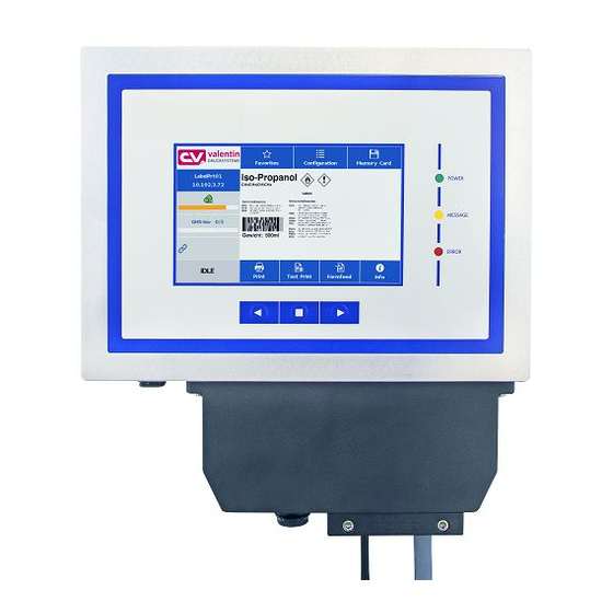
Dynacode II IP Touch-Screen Display 11 Touch-Screen Display 11.1 Touch-Sscreen Display Structure The touch-screen display shows an intuitive graphic user interface with well-defined symbols and buttons. The touch-screen display informs about the current device status and status of the print order, alerts in case of an error and indicates the device settings in the menu. -
Page 106: Different Menus
Touch-Screen Display Dynacode II IP 11.2 Different Menus Indication of main menus The selected (active) menu is highlighted on orange background. If a selected menu contains so-called submenus, these are blue highlighted. Different parameters are combined in a submenu. Indication of submenus The left display side shows the available submenus. -
Page 107: User-Defined Info Field
Dynacode II IP Touch-Screen Display 11.3 User-Defined Info Field From the predefined contents, the user can define the display of the user-defined info field (green). Select the menu Maintenance/System settings/User-defined info field to specify what is to be displayed in the user-defined info field. 03.21 Operating Manual... - Page 108 Touch-Screen Display Dynacode II IP Selection of parameters Standard: Horizontal display orientation: Empty info field Vertical display orientation: Indication of job info (label name and number of printed labels) Job info: Indication of label names and the number of already printed IP configuration: Indication of IP address and MAC address of printing system...
-
Page 109: Favorites List
Dynacode II IP Touch-Screen Display 11.4 Favorites List Add parameters to favorites Press long (2 s) on a parameter (e.g. print speed) to display the appropriate selection. Press Add to favorites to add the selected parameter to the favorites list. 03.21 Operating Manual... - Page 110 Touch-Screen Display Dynacode II IP Remove parameters from favorites Press long (2 s) on a parameter (e.g. print speed) to display the appropriate selection. Press Remove from favorites to remove the selected parameter from the favorites list. Operating Manual 03.21...
-
Page 111: Parameter Input
Dynacode II IP Touch-Screen Display 11.5 Parameter Input Parameter input Numeric input In the header of input dialog the name of the parameter and the permissible value range are shown. The input is checked for validity. If the entered value not permissible, the button is blocked. - Page 112 Touch-Screen Display Dynacode II IP Selection from list Select the parameter for which you want to change the selection. The currently selected value is highlighted on orange background. Press to confirm the selection. Alphanumeric input The alphanumeric input is shown in the header of input dialog. Press to confirm the selection.
-
Page 113: Navigation Zones
Dynacode II IP Touch-Screen Display 11.6 Navigation Zones The respective navigation zone can be moved with an appropriate swipe movement from top to bottom or from the bottom up. NOTE! With the used resistive touch screen variant, a certain pressure on the display is needed. -
Page 114: Maintenance Zone
Touch-Screen Display Dynacode II IP 11.7 Maintenance Zone Different settings for the display indication can be done. Maintenance - Print preview Print preview With activated print preview a picture of the currently printed layout is activated On/Off shown on the display. If the function is not activated, the field remains empty. - Page 115 Dynacode II IP Touch-Screen Display Print preview – Zoom Selection of a certain zoom value for the representation of print preview. Label: The complete layout is fit to the indication zone. Fields: Only the print range is fit to the indication zone. 1 ..
- Page 116 Touch-Screen Display Dynacode II IP Print preview – Interval During a running print order the preview is refreshed in the set interval. Value range: 0 .. 10 seconds In the LCD maintenance sector, different parameters to the touch- Maintenance - LCD screeen display can be set.
- Page 117 Dynacode II IP Touch-Screen Display LCD – Backlight Setting the brightness of background lighting. Value range: 0 .. 100 %. LCD - Orientation Landscape 180°: The display is represented turned by 180 degres to the function 'Landscape'. Landscape: The display is represented turned by 90 degres to the reading direction.
- Page 118 Touch-Screen Display Dynacode II IP Maintenance - System settings Different system settings such as set printer type, reset paper counter etc. can be made. However, for the settings the corresponding password is necessary. Operating Manual 03.21...
-
Page 119: Process Data
Dynacode II IP Touch-Screen Display 11.8 Process Data Activation of display for process data In order to show the process data, the parameter must be activated before in the menu Maintenance/Print preview. Add parameter to process data Press long (2 s) on a parameter (e.g. current time) to display the appropriate selection. - Page 120 Touch-Screen Display Dynacode II IP Remove parameter from process data Press long (2 s) on a parameter (e.g. current time) to display the appropriate selection. Press Remove from process data to remove the selected parameter from the process data list. Change of display vies With activated print preview, the display shows a picture of the Process data –...
-
Page 121: Memory Menu
Dynacode II IP Touch-Screen Display 11.9 Memory Menu Compact Flash Card On the left side, the content of the currently selected directory is shown one below the other. USB Stick The preview zone in on the right side is. If available, the preview of the selected layout is shown. - Page 122 Touch-Screen Display Dynacode II IP The user query can be entered at the cursor position. Press to change to the input of number of copies. Number of copies Enter the number of layouts to be printed. Operating Manual 03.21...
-
Page 123: Information Zone
Dynacode II IP Touch-Screen Display 11.10 Information Zone By pressing the Info button the versions of the installed components are displayed. By pressing the Info button once more, the Home view is again displayed. 11.11 Change to Foil Keyboard Press long (> 3 s) on the company logo left above, and the display changes to the indication of a conventionalized foil keyboard. - Page 124 Touch-Screen Display Dynacode II IP Operating Manual 03.21...
-
Page 125: Maintenance And Cleaning
Dynacode II IP Maintenance and Cleaning 12 Maintenance and Cleaning DANGER! Risk of death by electric shock! Before opening the housing cover, disconnect the printing system from the mains supply and wait for a moment until the power supply unit has discharged. NOTICE! When cleaning the label printer, personal protective equipment such as safety goggles and gloves are recommended. -
Page 126: Clean The Transfer Ribbon Roller
Maintenance and Cleaning Dynacode II IP 12.2 Clean the Transfer Ribbon Roller A soiled ribbon roller can lead to reduced print quality and can affect transport of material. Figure 23 1. Remove the transfer ribbon cassette. 2. Remove deposits with the roller cleaner and a soft cloth. 3. -
Page 127: Replace The Printhead
Dynacode II IP Maintenance and Cleaning 12.4 Replace the Printhead CAUTION! The printhead can be damaged by static electricity discharges and impacts! Set up the device on a grounded, conductive surface. Ground your body, e.g. by wearing a grounded wristband. ... - Page 128 Maintenance and Cleaning Dynacode II IP Figure 25 Install the printhead 1. Insert the connection assembly to the new printhead. 2. Position the printhead in the printhead support (A), so the engaging pieces catch in the appropriate holes in the printhead support (A).
-
Page 129: Angle Adjustment (Intermittent Mode)
Dynacode II IP Maintenance and Cleaning 12.5 Angle Adjustment (Intermittent Mode) Figure 26 The installation angle of the printhead is default 26° to the print surface. However, manufacturing tolerances of printhead and mechanics can require another angle. CAUTION! Damage of printhead by unequal use! Higher wastage of ribbon by faster ripping. -
Page 130: Print Quality Optimisation
Maintenance and Cleaning Dynacode II IP 12.6 Print Quality Optimisation The following table shows some possibilities to improve the print quality. Generally you have to note: the higher the print speed the lower the print quality. Problem Mögliche Behebung • Regular inferior print quality Increase the contrast •... -
Page 131: Cycle Optimisation (Intermittent Mode)
Dynacode II IP Maintenance and Cleaning 12.7 Cycle Optimisation (Intermittent Mode) NOTICE! The cycle is a finished print cycle per a unit of time. Figure 27 In case of 'time critical' applications you have the possibility with a good selection of different device parameters to increase the effective print speed and it this way the clock cycle. - Page 132 Maintenance and Cleaning Dynacode II IP Operating Manual 03.21...
-
Page 133: Signal Diagrams
Dynacode II IP Signal Diagrams 13 Signal Diagrams 13.1 Continuous Mode NOTICE! The line 'data receipt' indicates when the direct print module receives data. Dispenser mode: Number of layouts per print order: 1 Data memory: standard Dynamic Ribbon saving: On Trigger input print start: increasing slope Figure 28 In 'dispenser mode: dynamic' the layout distance onto the material is... - Page 134 Signal Diagrams Dynacode II IP Number of layouts per print order: 1 Data memory: extended Ribbon saving: On Trigger input print start: increasing slope Figure 29 Layout For a better comparison we used the same layouts as before. As soon as the generation of the layout is finished a new one is send Data receipt to the direct print module.
- Page 135 Dynacode II IP Signal Diagrams Number of layouts per print order: 3 Data memory: Off/standard/extended Ribbon saving: On Trigger input print start: increasing slope Figure 30 Layout/generation with The use of printer variables means that each layout is different and the direct print module has to generate several parts of the layout module variables anew, e.g.
- Page 136 Signal Diagrams Dynacode II IP Number of layouts per print order: 4 Dispenser Mode: Static Data memory: Off/standard/extended Ribbon saving: On Trigger input print start: level High Figure 31 Layout 4 layouts with counter. In 'dispenser mode: static' the level of the start impulse is recognised Print start/print as valid start signal.
-
Page 137: Intermittent Mode
Dynacode II IP Signal Diagrams 13.2 Intermittent Mode Mode 1 (single item processing) Figure 32 Mode 2 (continuous mode) Figure 33 03.21 Operating Manual... - Page 138 Signal Diagrams Dynacode II IP Operating Manual 03.21...
-
Page 139: Error Correction
Dynacode II IP Error Correction 14 Error Correction Error message Cause Remedy Line too high Line rises up completely or Move line down (increase Y partly over the upper edge of value). label. Check rotation and font. Line too low Line rises up completely or Move line up (reduce Y value). - Page 140 Error Correction Dynacode II IP Error message Cause Remedy Field number Received line number is invalid. Check sent data. Check connection PC - printer. Length mask Invalid length of received mask Check sent data. statement. Check connection PC - printer. Unknown mask Transferred mask statement is Check sent data.
- Page 141 Dynacode II IP Error Correction Error message Cause Remedy Application Selected application identifier is Check code data. Identifier not available in GS1-128. HIBC definition Missing HIBC system sign. Check definition of HIBC code. Missing primary code. System clock Real Time Clock function is Change battery.
- Page 142 Error Correction Dynacode II IP Error message Cause Remedy Drive write- Memory card is write-protected. Deactivate write protection. protected Directory not file Attempt to indicate a directory Correct your entry. as file name. File already open Attempt to change a file during Select another file.
- Page 143 Dynacode II IP Error Correction Error message Cause Remedy Zero point Defective photocell. Change photocell. Compressed air Pressure air is not connected. Check pressure air. External release External print release signal is Check input signal. missing. Column too wide Wrong definition of column Reduce the column width res.
- Page 144 Error Correction Dynacode II IP Error message Cause Remedy Time generation Printing creation was still active Reduce print speed. at print start. Use printers' output signal for synchronization. Use bitmap fonts to reduce generating time. Transport protection Both DPM position sensors Displace zero point sensor (start/end) are active.
- Page 145 Dynacode II IP Error Correction Error message Cause Remedy Scanner layout Scanner data does not Check adjustment of scanner. difference correspond to bar code data. Check scanner settings / connection. COM break Serial interface error. Check settings for serial data transmission as well as cable (printer-PC).
- Page 146 Error Correction Dynacode II IP Error message Cause Remedy Housing open When starting the print order Close the housing cover and the housing cover is not closed. start the print order anew. EAN.UCC code Transferred EAN.UCC code is Verify bar code data (see invalid.
- Page 147 Dynacode II IP Error Correction Error message Cause Remedy Print asynchronous The label photocell does not Check label size and gap size. work in the order as it is expected according to print data. The settings of the photocell Check label photocell settings. are not correct.
- Page 148 Error Correction Dynacode II IP Error message Cause Remedy Script user error Error in LUA script user input. Correct the input value. No reprint available No label data for reprinting Send new label data to the available. printer. Printhead short Electrical short at the printhead.
-
Page 149: Additional Information
Dynacode II IP Additional Information 15 Additional Information 15.1 Hotstart NOTICE! The data is saved onto CF card. Therefore the CF card is a condition for the Hotstart menu item. The function Hotstart contains e.g. that in case of a power failure the currently loaded layout can be further processed without any loss of data. - Page 150 Additional Information Dynacode II IP In case at switching off the direct print module a print order was Start print order active, then a print start is released automatically and the required res. actual number of printed layouts is refreshed. In case the print order was stopped at switching off the direct print module, it is again set to the stopped mode after switching on the direct print module anew.
-
Page 151: Cycles For The Continuous Mode
Example 2: Bag length: 300 mm Print length: 40 mm What is the maximum print speed for Dynacode II IP53? sa = 300 mm - 40 mm = 260 mm Search in the tables for sa: 260 mm The table Dynacode II IP c53, transfer ribbon length 900 m (page 151) indicates that the maximum print speed is approx. - Page 152 Dynacode II IP Cycles in continuous Transfer ribbon length mode for 900 m 600 m 450 m 300 m Speed in Dynacode II IP53 mm/s sa in mm sa in mm sa in mm sa in mm Operating Manual 03.21...
- Page 153 Dynacode II IP Additional Information Transfer ribbon length 900 m 600 m 450 m 300 m Speed in mm/s sa in mm sa in mm sa in mm sa in mm 03.21 Operating Manual...
- Page 154 Additional Information Dynacode II IP Cycles in continuous Transfer ribbon length mode for 600 m 450 m 300 m Speed in Dynacode II IP107 mm/s sa in mm sa in mm sa in mm Operating Manual 03.21...
- Page 155 Dynacode II IP Additional Information Transfer ribbon length 600 m 450 m 300 m Speed in mm/s sa in mm sa in mm sa in mm 03.21 Operating Manual...
- Page 156 Additional Information Dynacode II IP Cycles in continuous Transfer ribbon length mode for 450 m 300 m Speed in Dynacode II IP128 mm/s sa in mm sa in mm Operating Manual 03.21...
-
Page 157: Cycles For The Intermittent Mode
Dynacode II IP Additional Information 15.3 Cycles for the intermittent mode Dynacode II IP53: C = cycles per minute Transfer ribbon length tP = print tB = return 900 m Back speed = 600 mm/s 315 260 230 206 193 181 171 162... - Page 158 Additional Information Dynacode II IP Dynacode II IP107: C = cycles per minute tP = print Transfer ribbon length 600 m tB = return Back speed = 600 mm/s 285 240 206 187 176 162 153 146 130 140 160 170 180 190 200 210 80 110 130 150 160 180 190 200 285 240 206 187 176 162 153 146 130 140 160 170 180 190 200 210...
- Page 159 Dynacode II IP Additional Information Dynacode II IP128 C = cycles per minute tP = print Transfer ribbon length 450 m tB = return Back speed = 600 mm/s 285 240 206 187 176 162 153 146 130 140 160 170 180 190 200 210 80 110 130 150 160 180 190 200 285 240 206 187 176 162 153 146 130 140 160 170 180 190 200 210...
- Page 160 Additional Information Dynacode II IP Operating Manual 03.21...
-
Page 161: Environmentally-Friendly Disposal
Carl Valentin GmbH zurückgegeben werden. Die Altgeräte werden daraufhin fachgerecht entsorgt. Die Carl Valentin GmbH nimmt dadurch alle Verpflichtungen im Rahmen der Altgeräteentsorgung rechtzeitig wahr und ermöglicht damit auch weiterhin den reibungslosen Vertrieb der Produkte. Wir können nur frachtfrei zugesandte Geräte zurücknehmen. - Page 162 Environmentally-Friendly Disposal Dynacode II IP Operating Manual 03.21...
-
Page 163: Index
Dynacode II IP Index 17 Index clamping force (ribbon roll)............... 45 cleaning cassette Illustration ..................47 using .................... 48 connection ..................41 connection side of print mechanics ..........11 connector assignment of control unit ..........12 continuous mode material guiding ................14 material speed ................ - Page 164 Index Dynacode II IP main menu ................92, 104 maintenance ..............103, 104 menu structure (continuous mode) ......49, 50, 51, 52, 53 menu structure (intermittent mode) ......54, 55, 56, 57, 58 network ..................92 password ................101, 102 print settings ................59 service functions ..........
- Page 165 Dynacode II IP Index password network ..................102 operation ..................102 pneumatic power supply, connection ..........36 pressure power, adjusting ..............40 print control ..................42 protective cover for control unit (IP 65), mounting....37, 38, 39 required space, cable outgoing ............35 ribbon saving ...................
- Page 166 Index Dynacode II IP navigation zones ................ 113 numeric input ................111 parameter input ................111 process data ..............119, 120 structure ..................105 submenus .................. 106 user-defined info field ............107, 108 transfer ribbon loading coating inside ................44 coating outside ................
- Page 168 Carl Valentin GmbH Neckarstraße 78 86 u. 94 . 78056 Villingen-Schwenningen Phone +49 7720 9712-0 . Fax +49 7720 9712-9901 info@carl-valentin.de . www.carl-valentin.de...
Need help?
Do you have a question about the DYNACODE II IP53 and is the answer not in the manual?
Questions and answers