Table of Contents
Advertisement
Advertisement
Table of Contents

Related Manuals for Kuppersbusch IKE 458-4-4T


Summary of Contents for Kuppersbusch IKE 458-4-4T
- Page 1 Technical Manual IKE 458-4-4T...
- Page 2 Service Manual: H8-03-02 Responsible: U. Laarmann KÜPPERSBUSCH HAUSGERÄTE AG E-mail: uwe.laarmann@kueppersbusch.de Phone: (0209) 401-732 Kundendienst Fax: (0209) 401-743 Postfach 100 132 Date: 10.10.2005 45801 Gelsenkirchen...
-
Page 3: Table Of Contents
Alarm freezer section door open ................. 25 Installation instructions ....................26 Adjusting the height..................... 26 Mounting the side panels ..................26 Installation of the doors ..................27 Installing the appliance..................29 Attaching the base....................29 10. Circuit diagram IKE 458-4-4T..................31 For internal use only... -
Page 4: Safety
H8-03-02 Safety Danger! Repairs may only be carried out by a qualified electrician! Inexpert repairs may lead to danger and injury to the user! To prevent electric shocks, please observe the following instructions: • In the event of a fault, housing and frame may be live! •... -
Page 5: General
H8-03-02 General This manual describes electronic refrigerators with four doors. This series is equipped with electronic control elements instead of electromechanical thermostats. There is no electromechanical timer because the electronics with the designation ERF2000 have an integrated electronic timer. Installation and connection Dry, well ventilated rooms present the best conditions for installing the fridge-freezers. -
Page 6: Technical Manual
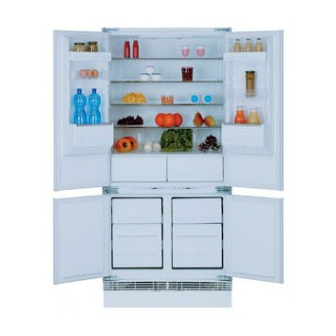
H8-03-02 Technical manual General structure of the appliance The electronic operating elements of the device are found inside the central transverse support. The fridge with 4 doors has 3 refrigeration zones available so that every type of food can be stored optimally. The appliance is equipped with two compressors and has two separate cooling circuits: View of the refrigeration section Cooling circuit of the zero-degree zone and the freezer section. -
Page 7: Air Circulation
H8-03-02 C – Freezer section The cold air is generated by a battery-operated evaporator, while the forced circulation of the air is affected by means of a ventilator. This means that moist air in the form of frost only condenses on the evaporator and not on the freezer walls or on food packages. -
Page 8: Components
H8-03-02 Components Refrigerator section compressor Freezer compressor Battery-operated evaporator Ventilator for the battery-operated evaporator Flap thermostat (only for some models) Flush-mounted refrigerator evaporator Thermal protection device Defroster resistor Condensation water channel resistor D.A.C. (only for some models). NTC probe of the freezer NTC probe of the battery-operated evaporator NTC probe of the refrigerator... - Page 9 H8-03-02 Defrost resistor The ice which builds up on the evaporator needs to be defrosted at regular intervals. To do this, approx. every 14 hours, the freezer electronics switch on a resistor (303 Ohm; 240 V) consuming 190 W which is in direct contact with the battery.
-
Page 10: Control Panel
H8-03-02 Control panel Freezer section Refrigerator section Freezer section key ON/OFF control lamp ON/OFF button of the freezer section Button to raise the temperature (+) Temperature display in the freezer section Button to decrease the temperature (-) Alarm lamp Button for switching off the alarm Superfrost function control lamp Button for the Superfrost function Refrigerator section key... -
Page 11: Electronics
H8-03-02 Electronics Freezer section Refrigerator section The appliance is controlled by two independent electronic systems: Electronic system of freezer section Electronic system of refrigerator section Freezer section ERF2000 electronic unit The freezer section electronics are type ERF2000 and comprise: Power electronics Display electronics The two electronic systems are connected by a ribbon cable with plug connectors and therefore they are available individually as replacement parts. - Page 12 H8-03-02 4.2.1 Power electronics (freezer section) View of the power electronics (components side): Earth contact Not used Cable Freezer section compressor Neutral wire Not used Not used Neutral wire Defrost resistor Ventilator for the battery-operated evaporator Not used For internal use only...
- Page 13 H8-03-02 Not used Not used Evaporator probe (black cable) Evaporator probe (black cable) Freezer probe (brown cable) Freezer probe (brown cable) Freezer section door switch Freezer section door switch Not used Not used Not used Not used Not used Not used For internal use only...
-
Page 14: Electronics For Refrigerator Erf2020
H8-03-02 4.2.2 Display electronics for freezer section = Button to switch off the alarm = Button for the superfrost function = Button to raise the temperature (+) = Button to decrease the temperature (-) = ON/OFF button for freezer = Reed element (optional) DS1 = Alarm control lamp DS2 = Control lamp for the superfrost function DS3 = Symbol (-) - Page 15 H8-03-02 4.3.1 Power electronics and display electronics (refrigerator) View of the power electronics (welded side): = Button for the supercool function = Button for the D.A.C. function (only for some models!) = Button to raise the temperature (+) = Button to decrease the temperature (-) = ON/OFF button for the refrigerator section = Reed element (optional) DS1 = Supercool control lamp...
- Page 16 H8-03-02 Cable Compressor of the refrigerator section Neutral wire Lamp Neutral wire Not used D.A.C. fan (only for some models). Neutral wire Not used Not used Not used Not used Refrigerator section probe (white cable) Refrigerator section probe (white cable) Evaporator probe (black cable) Evaporator probe (black cable) Not used...
-
Page 17: Functioning
H8-03-02 Functioning Normal (freezer section) The electronics are supplied with a 220-240 V / 50 Hz voltage, even when the appliance is switched off (OFF). Before the electronics are handled, therefore, the mains supply plug must be disconnected. Thanks to the air circulation, any humidity in the freezer section is collected on the evaporator battery and this prevents the formation of frost on the foodstuff. -
Page 18: Ventilator For The Battery-Operated Evaporator
H8-03-02 Ventilator for the battery-operated evaporator As long as the freezer doors are not opened, the ventilator of the battery-operated evaporator will run for as long as the compressor is running (when the compressor is switched off the ventilator will be deactivated after a 2 minute delay). -
Page 19: Malfunctioning Of The Refrigerator Air Temperature Probe
H8-03-02 Malfunctioning of the refrigerator air temperature probe Should the NTC temperature probe malfunction during normal operation (i.e. the signal from the probe falls outside the limiting values), then: • The appliance will follow a predetermined programme sequence during which the refrigerator compressor is alternately supplied for 30 minutes and then switched off for 40 minutes;... -
Page 20: Ntc Sensor Characteristics
H8-03-02 NTC sensor characteristics Conversion table For internal use only... -
Page 21: Access To The Individual Components
H8-03-02 Access to the individual components Freezer section Proceed as follows in order to access the components inside the freezer section: • Remove the trays from the guide rails. To do this rotate the stops as shown on the diagram: •... -
Page 22: Replacing The Flap Thermostat
H8-03-02 Replacing the flap thermostat Unhook the thermostat bulb and then remove the screws with which the thermostat is attached to the cell. Defrost resistor Remove the screws with which the battery-operated evaporator is fastened to the bottom of the cell. Carefully tilt the battery, making sure that the leads are not damaged. -
Page 23: Customer Service Program - Freezer Section
H8 03 02 Cust er service pr gra – free er secti Start of the customer service program To start the customer service program, proceed as follows: Insert the plug into the mains socket. Switch off the appliance at the ON/OFF button (A) (both freezer and refrigerator section). Pull out the mains plug. - Page 24 H8-03-02 The load controlled by acs TH3 [not used with this appliance] is checked (the number 2 is shown as the right-hand digit of the display). For activating/deactivating the load press the “superfrost function” button; The load controlled by acs TH4 [ventilator of the battery-operated evaporator] is checked (the number 3 is shown as the right-hand digit of the display).
-
Page 25: Alarm Indication
H8-03-02 Alarm indication Alarm freezer temperature When a temperature of -8 °C is reached in the freezer section the temperature alarm is activated and • the control lamp associated with the alarm will flash; • the temperature display will flash; •... -
Page 26: Installation Instructions
H8-03-02 Installation instructions Adjusting the height The height of the appliance can be matched to that of the other kitchen units by adjusting it to 820 mm or to 870 mm. Prior to installing the appliance, set the height of the rear wheels and feet. -
Page 27: Installation Of The Doors
H8-03-02 Attach the rear brackets, taking into account the depth of the side wall and the external furniture dimension of 900 mm. During installation observe that the appliance's housing edge must be 45 mm from the edge of the kitchen furniture. Fasten the panels at the front. - Page 28 H8-03-02 Then close the door and check that it is at the desired height. If necessary, adjust using the adjustment screws on the disk and the hinge. The same adjustment screws are also used for vertically aligning the doors. Check the horizontal alignment of the doors and if necessary adjust their position at the long holes.
-
Page 29: Installing The Appliance
H8-03-02 Installing the appliance Fasten it to the wall with the angle bracket provided provided for this purpose. In order to allow good air circulation, do not cover the top of the appliance. Should a kitchen unit be installed above the appliance, it is to be fastened 50 mm from the wall. - Page 30 H8-03-02 Height adjustment H = 870 mm For a base of 190 to 220 mm, make an opening as shown. If the base is higher than 150 mm and lower than 190 mm, cut the compensation cover piece accordingly and mount it between the base and the ventilation grid.
-
Page 31: Circuit Diagram Ike 458-4-4T
H8-03-02 For internal use only... - Page 32 H8-03-02 Terminal board Refrigerator section compressor Freezer section compressor Motor protection switch Defroster resistor Condensation water channel resistor Refrigerator lamp Refrigerator door switch Freezer section door switch Battery-operated evaporator ventilator 24a. D.A.C. ventilator Overheating protection switch (+40 °C) Overheating protection switch (+40 °C) Operation condenser (only with models where it is provided) Refrigerator section (ERF2020) electronics 41a.
Need help?
Do you have a question about the IKE 458-4-4T and is the answer not in the manual?
Questions and answers